Exhaust Heat Recirculation System Circuit [12/2019 - ]: Description
In the exhaust heat recirculation system, coolant is warmed up using conventionally wasted exhaust gas heat to accelerate engine warm-up time, enhancing fuel efficiency and heater performance.
The heat recirculator is positioned in the front exhaust pipe assembly after the catalyst. Coolant from the engine flows around the heat recirculator and then returns to the engine. If the engine is started while the engine is cold, the exhaust pipe gas control actuator rod is contracted and the exhaust flow control valve is closed, routing the exhaust gas around the heat recirculator to warm up the coolant.
After the engine coolant temperature rises and the engine has warmed up, the heat of the coolant expands the thermostat and the exhaust pipe gas control actuator rod extends. This opens the exhaust flow control valve to switch to the normal exhaust gas path.
The exhaust flow control valve can also be opened by exhaust gas pressure to prevent insufficient acceleration performance when the engine is cold. In addition, to monitor the engine coolant temperature, an engine coolant temperature sensor (for exhaust heat recirculation system) is provided between the engine and the heat recirculator. The engine coolant temperature sensor (for exhaust heat recirculation system) has a built-in thermistor with a resistance that varies according to the temperature of the engine coolant. When the engine coolant temperature becomes low, the resistance of the thermistor increases. When the temperature becomes high, the resistance drops. These variations in resistance are transmitted to the combination meter assembly as voltage changes. If the engine coolant temperature is excessively high (overheating), the water temperature indicator light in the combination meter assembly illuminate to inform the driver of the malfunction.
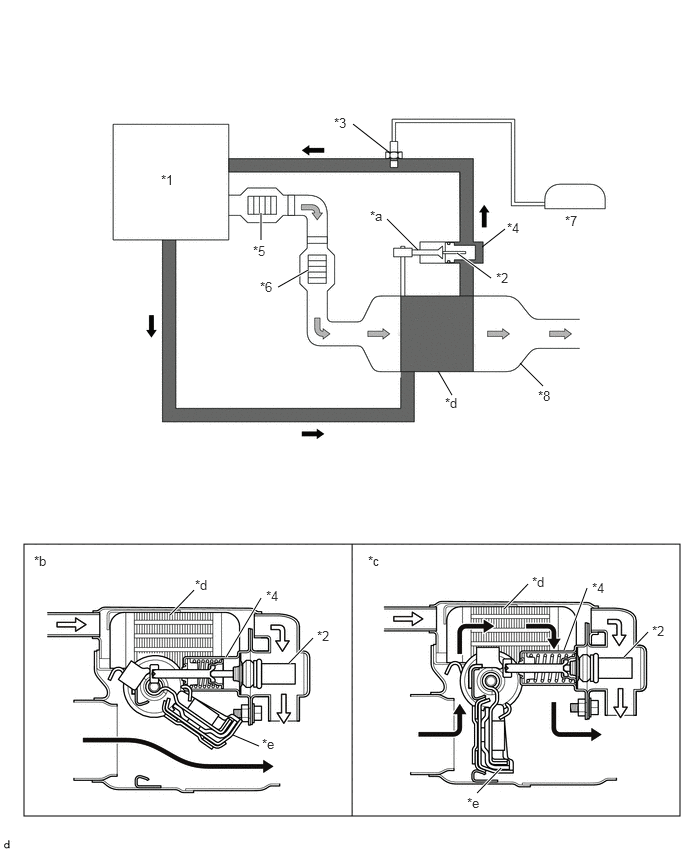
| *1 | Engine Assembly | *2 | Thermostat |
| *3 | Temperature Switch (for Exhaust Heat Recirculation System) | *4 | Exhaust Pipe Gas Control Actuator |
| *5 | Front Catalyst | *6 | Rear Catalyst |
| *7 | Combination Meter Assembly | *8 | Front Exhaust Pipe Assembly |
| *a | Rod | *b | Exhaust Flow Control Valve Open |
| *c | Exhaust Flow Control Valve Closed | *d | Heat Recirculator |
| *e | Exhaust Flow Control Valve | - | - |
 |
Exhaust Gas |  |
Engine Coolant |