DTC C14C9-A2: Electronic Brake Booster Control Module "A" System Voltage Low [12/2019 - 10/2021]: Procedure
WARNING: This page is about a different variant/trim than selected.
- CHECK DTC
- Check the DTCs that are output.
Chassis > Brake Booster > Trouble Codes
Chassis > Brake/EPB > Trouble Codes
Result
Result Proceed to Only DTC C14C9-A2 is output. A DTCs other than C14C9-A2 are output. B
Result:
B
REPAIR CIRCUITS INDICATED BY OUTPUT DTCS. Refer to DIAGNOSTIC TROUBLE CODE CHART [12/2019 - 10/2021]
Result:
A
See step 2
- Check the DTCs that are output.
- READ VALUE USING GTS (+BI1 VOLTAGE)
- Drive the pump motor by performing the Active Test.
HINT:
- The pump motor can be driven by performing the Active Test for ECB* solenoid (SLA).
*: Electronically Controlled Brake System
- Perform the Active Test with the current set to maximum.
- The pump motor can be driven by performing the Active Test for ECB* solenoid (SLA).
- Monitor the value of Data List item +BI1 Voltage when the pump motor is being driven.
Chassis > Brake Booster > Active Test
Tester Display Measurement Item Control Range Restrict Condition Diagnostic Note ECB Solenoid (SLA) Linear solenoid addition valve (SLA) Solenoid Start (Activate)
Solenoid SLA
(It is possible to set the current)Vehicle condition: - Vehicle stopped
- Shift lever is in P
- Apply the parking brake
ECB: Electronically Controlled Brake System Chassis > Brake Booster > Data List
Tester Display Measurement Item Range Normal Condition Diagnostic Note BI Voltage +BI1 voltage value Min.: 0.000 V
Max.: 20.000 V- Changes in proportion to auxiliary battery voltage Chassis > Brake Booster > Active Test
Active Test Display ECB Solenoid (SLA) Data List Display BI Voltage Result
Result Proceed to +BI1 voltage is 11 to 14 V. A +BI1 voltage is below 11 V. B
Result:
A
USE SIMULATION METHOD TO CHECK. Refer to HOW TO PROCEED WITH TROUBLESHOOTING [12/2019 - ]
Result:
B
See step 3
- Drive the pump motor by performing the Active Test.
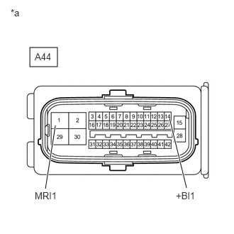
- CHECK HARNESS AND CONNECTOR (+BI1 AND MRI1 TERMINAL)
- Turn the ignition switch off.
*a Front view of wire harness connector
(to No. 1 Skid Control ECU (Brake Booster with Master Cylinder Assembly)) - Make sure that there is no looseness at the locking part and the connecting part of the connector.
OK
The connector is securely connected.
- Disconnect the A44 No. 1 skid control ECU (brake booster with master cylinder assembly) connector.
- Check both the connector case and the terminals for deformation and corrosion.
OK
No deformation or corrosion.
- Measure the voltage according to the value(s) in the table below.
Standard Voltage
Tester Connection Condition Specified Condition A44-14 (+BI1) - Body ground Always 11 to 14 V A44-1 (MRI1) - Body ground Always 11 to 14 V Result
Result Proceed to 11 to 14 V. A Below 11 V. B
Result:
A
REPLACE BRAKE BOOSTER WITH MASTER CYLINDER ASSEMBLY. Refer to REMOVAL [12/2019 - 10/2022]
Result:
B
REPAIR OR REPLACE HARNESS OR CONNECTOR
- Turn the ignition switch off.