DTC C141C-12: Brake Booster Motor "A" Control Circuit Short to Battery; DTC C141C-14: Brake Booster Motor "A" Control Circuit Short to Ground or Open; DTC C141C-1C: Brake Booster Motor "A" Control Circuit Voltage Out of Range [11/2023 - ]: Procedure
- CHECK DTC
- Check the DTCs that are output.
Chassis > Brake Booster > Trouble Codes
Chassis > Brake/EPB > Trouble Codes
Result
Result Proceed to DTCs C141C-12, C141C-14 and/or C141C-1C are output. A DTCs other than C141C-12, C141C-14 and C141C-1C are output. B
Result:
B
REPAIR CIRCUITS INDICATED BY OUTPUT DTCS. Refer to DIAGNOSTIC TROUBLE CODE CHART [11/2023 - ]
Result:
A
See step 2
- Check the DTCs that are output.
- READ VALUE USING GTS (MOTOR RELAY)
- Depress the brake pedal several times and check the operation status of the motor relay.
Chassis > Brake Booster > Data List
Tester Display Measurement Item Range Normal Condition Diagnostic Note ECB Motor Relay Motor relay operation request OFF / ON OFF: Relay off
ON: Relay onECB: Electronically Controlled Brake System Chassis > Brake Booster > Data List
Tester Display ECB Motor Relay HINT:
Depressing the brake pedal several times drops the accumulator pressure and operates the pump motor.
Result
Result Proceed to The status of motor relay in the Data List turns on and off after depressing the brake pedal several times. A The status of motor relay in the Data List does not change even after depressing the brake pedal several times. B
Result:
B
See step 10
Result:
A
See step 3
- Depress the brake pedal several times and check the operation status of the motor relay.
- INSPECT BRAKE BOOSTER WITH ACCUMULATOR PUMP ASSEMBLY
- Turn the ignition switch off.
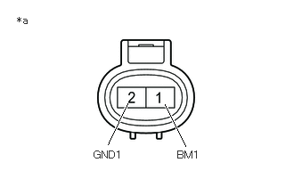
*a Component without harness connected
(Brake Booster with Accumulator Pump Assembly) - Make sure that there is no looseness at the locking part and the connecting part of the connector.
OK
The connector is securely connected.
- Disconnect the A9 brake booster with accumulator pump assembly connector.
- Check both the connector case and the terminals for deformation and corrosion.
OK
No deformation or corrosion.
- Measure the resistance according to the value(s) in the table below.
Standard Resistance
Tester Connection Condition Specified Condition 1 (BM1) - 2 (GND1) Always 10 Ω or less Result
Proceed to OK NG
Result:
NG
REPLACE BRAKE BOOSTER WITH ACCUMULATOR PUMP ASSEMBLY. Refer to REMOVAL [11/2023 - ]
Result:
OK
See step 4
- Turn the ignition switch off.
- CHECK HARNESS AND CONNECTOR (BRAKE BOOSTER WITH MASTER CYLINDER ASSEMBLY - BRAKE BOOSTER WITH ACCUMULATOR PUMP ASSEMBLY)
- Make sure that there is no looseness at the locking part and the connecting part of the connector.
OK
The connector is securely connected.
- Disconnect the A44 No. 1 skid control ECU (brake booster with master cylinder assembly) connector.
- Check both the connector case and the terminals for deformation and corrosion.
OK
No deformation or corrosion.
- Measure the resistance according to the value(s) in the table below.
Standard Resistance
Tester Connection Condition Specified Condition A9-2 (GND1) - A44-30 (M-) Always Below 1 Ω Result
Proceed to OK NG
Result:
NG
REPAIR OR REPLACE HARNESS OR CONNECTOR
Result:
OK
See step 5
- Make sure that there is no looseness at the locking part and the connecting part of the connector.
- READ VALUE USING GTS (ACCUMULATOR PRESSURE)
- Reconnect the A9 brake booster with accumulator pump assembly connector.
- Reconnect the A44 No. 1 skid control ECU (brake booster with master cylinder assembly) connector.
- Disconnect the A90 brake pedal stroke sensor assembly connector.
- Depress the brake pedal several times to operate the pump motor, then wait until it stops.
- After the pump motor stops, wait for 30 seconds, then check the drop in the accumulator pressure sensor output value and the state of the pump motor.
Chassis > Brake Booster > Data List
Tester Display Measurement Item Range Normal Condition Diagnostic Note ECB Motor Relay Motor relay operation request OFF / ON OFF: Relay off
ON: Relay onECB: Electronically Controlled Brake System Accumulator Pressure Accumulator pressure output value Min.: 0.00 MPa
Max.: 24.48 MPa15.00 to 21.00 MPa (Pressure stable and pump motor stopped) When brake fluid is stored in the accumulator: Accumulator pressure changes in accordance with volume of fluid stored in the accumulator Chassis > Brake Booster > Data List
Tester Display ECB Motor Relay Accumulator Pressure HINT:
- This inspection checks whether an accumulator pressure sensor malfunction, internal brake booster with master cylinder assembly leak or prolonged operation due to detection of low pressure caused by accumulator deterioration, caused the DTC to be stored.
- If the brake fluid level in the brake master cylinder reservoir assembly drops, an external brake fluid leak is suspected.
Result
Result Proceed to The drop in the accumulator pressure sensor output value is less than 2.50 MPa 30 seconds after the pump motor stops, and the pump motor does not operate within 30 seconds after the pump motor stops. A The drop in the accumulator pressure sensor output value is 2.50 MPa or more 30 seconds after the pump motor stops, or the pump motor operates within 30 seconds after the pump motor stops. B
Result:
B
See step 8
Result:
A
See step 6
- CLEAR DTC
- Turn the ignition switch off.
- Reconnect the A90 brake pedal stroke sensor assembly connector.
- Clear the DTCs.
Chassis > Brake Booster > Clear DTCs
- Turn the ignition switch off.
Result
Proceed to NEXT
Result:
NEXT
See step 7
- RECONFIRM DTC
- Based on the Freeze Frame Data and interview with the customer, attempt to reproduce the conditions when the malfunction occurred.
- Check if the same DTC is output.
Chassis > Brake Booster > Trouble Codes
Result
Result Proceed to DTCs C141C-12, C141C-14 and C141C-1C are not output. A DTCs C141C-12, C141C-14 and/or C141C-1C are output. B
Result:
A
USE SIMULATION METHOD TO CHECK. Refer to HOW TO PROCEED WITH TROUBLESHOOTING [12/2019 - ]
Result:
B
REPLACE BRAKE BOOSTER WITH MASTER CYLINDER ASSEMBLY. Refer to REMOVAL [11/2023 - ]
- READ VALUE USING GTS (ACCUMULATOR PRESSURE)
- Turn the ignition switch off.
- Reconnect the A90 brake pedal stroke sensor assembly connector.
- Drive the linear solenoid (SLA) by performing the Active Test to reduce the accumulator pressure.
HINT:
Perform the Active Test with the current set to maximum.
- After reducing the accumulator pressure, confirm that the pump motor starts and the accumulator pressure returns to 15.00 to 21.00 MPa.
Chassis > Brake Booster > Active Test
Tester Display Measurement Item Control Range Restrict Condition Diagnostic Note ECB Solenoid (SLA) Linear solenoid addition valve (SLA) Solenoid Start (Activate)
Solenoid SLA
(It is possible to set the current)Vehicle condition: - Vehicle stopped
- Shift lever is in P
- Apply the parking brake
ECB: Electronically Controlled Brake System Chassis > Brake Booster > Data List
Tester Display Measurement Item Range Normal Condition Diagnostic Note Accumulator Pressure Accumulator pressure output value Min.: 0.00 MPa
Max.: 24.48 MPa15.00 to 21.00 MPa (Pressure stable and pump motor stopped) When brake fluid is stored in the accumulator: Accumulator pressure changes in accordance with volume of fluid stored in the accumulator Chassis > Brake Booster > Active Test
Active Test Display ECB Solenoid (SLA) Data List Display Accumulator Pressure OK
The accumulator pressure reduces, and then returns to 15.00 to 21.00 MPa when the pump motor operates.
Result
Proceed to OK NG
Result:
NG
REPLACE BRAKE BOOSTER WITH MASTER CYLINDER ASSEMBLY. Refer to REMOVAL [11/2023 - ]
Result:
OK
See step 9
- RECONFIRM DTC
- Confirm that the pump motor inside the brake booster with accumulator pump assembly is stopped.
- Based on the Freeze Frame Data and interview with the customer, attempt to reproduce the conditions when the malfunction occurred.
- Check if the same DTC is output.
Chassis > Brake Booster > Trouble Codes
Result
Result Proceed to DTCs C141C-12, C141C-14 and C141C-1C are not output. A DTCs C141C-12, C141C-14 and/or C141C-1C are output. B
Result:
A
USE SIMULATION METHOD TO CHECK. Refer to HOW TO PROCEED WITH TROUBLESHOOTING [12/2019 - ]
Result:
B
REPLACE BRAKE BOOSTER WITH MASTER CYLINDER ASSEMBLY. Refer to REMOVAL [11/2023 - ]
- CHECK HARNESS AND CONNECTOR (MRI1 TERMINAL)
- Turn the ignition switch off.
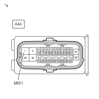
*a Front view of wire harness connector
(to No. 1 Skid Control ECU (Brake Booster with Master Cylinder Assembly)) - Make sure that there is no looseness at the locking part and the connecting part of the connector.
OK
The connector is securely connected.
- Disconnect the A44 No. 1 skid control ECU (brake booster with master cylinder assembly) connector.
- Check both the connector case and the terminals for deformation and corrosion.
OK
No deformation or corrosion.
- Measure the voltage according to the value(s) in the table below.
Standard Voltage
Tester Connection Condition Specified Condition A44-1 (MRI1) - Body ground Always 11 to 14 V Result
Proceed to OK NG
Result:
NG
REPAIR OR REPLACE HARNESS OR CONNECTOR
Result:
OK
See step 11
- Turn the ignition switch off.
- CHECK HARNESS AND CONNECTOR (BRAKE BOOSTER WITH MASTER CYLINDER ASSEMBLY - BRAKE BOOSTER WITH ACCUMULATOR PUMP ASSEMBLY)
- Make sure that there is no looseness at the locking part and the connecting part of the connector.
OK
The connector is securely connected.
- Disconnect the A9 brake booster with accumulator pump assembly connector.
- Check both the connector case and the terminals for deformation and corrosion.
OK
No deformation or corrosion.
- Measure the resistance according to the value(s) in the table below.
Standard Resistance
Tester Connection Condition Specified Condition A44-29 (M+) - A9-1 (BM1) Always Below 1 Ω A44-29 (M+) or A9-1 (BM1) - Body ground Always 10 kΩ or higher Result
Proceed to OK NG
Result:
OK
REPLACE BRAKE BOOSTER WITH MASTER CYLINDER ASSEMBLY. Refer to REMOVAL [11/2023 - ]
Result:
NG
REPAIR OR REPLACE HARNESS OR CONNECTOR
- Make sure that there is no looseness at the locking part and the connecting part of the connector.