DTC C12F8-12: ECB Solenoid Control "A" Circuit Short to Battery; DTC C12F8-14: ECB Solenoid Control "A" Circuit Short to Ground or Open [11/2023 - ]: Procedure
- READ VALUE USING GTS (BS VOLTAGE)
- Perform the Active Test and operate the main relay.
- Monitor the value of BS Voltage when the Active Test is being performed.
Chassis > Brake Booster > Active Test
Tester Display Measurement Item Control Range Restrict Condition Diagnostic Note ECB Main Relay Main relay OFF / ON Vehicle condition: Vehicle stopped
HINT:
To protect this Actuator and Solenoid, this test will only last 5 seconds.ECB: Electronically Controlled Brake System Chassis > Brake Booster > Data List
Tester Display Measurement Item Range Normal Condition Diagnostic Note BS Voltage BS voltage value Min.: 0.0 V
Max.: 25.5 V- Changes in proportion to auxiliary battery voltage Chassis > Brake Booster > Active Test
Active Test Display ECB Main Relay Data List Display BS Voltage Result
Result Proceed to During the Active Test, the voltage indicated by BS Voltage increases to the approximate voltage of the auxiliary battery. A During the Active Test, the voltage indicated by BS Voltage remains low around 0 V. B HINT:
During the Active Test, the voltage indicated by BS Voltage changes in proportion to the voltage of the auxiliary battery.
Result:
B
See step 4
Result:
A
See step 2
- CLEAR DTC
- Clear the DTCs.
Chassis > Brake Booster > Clear DTCs
- Turn the ignition switch off.
Result
Proceed to NEXT
Result:
NEXT
See step 3
- Clear the DTCs.
- RECONFIRM DTC
- Based on the Freeze Frame Data and interview with the customer, attempt to reproduce the conditions when the malfunction occurred.
- Check if the same DTC is output.
Chassis > Brake Booster > Trouble Codes
Result
Result Proceed to DTCs C12F8-12 and C12F8-14 are not output. A DTCs C12F8-12 and/or C12F8-14 are output. B
Result:
A
USE SIMULATION METHOD TO CHECK. Refer to HOW TO PROCEED WITH TROUBLESHOOTING [12/2019 - ]
Result:
B
REPLACE BRAKE BOOSTER WITH MASTER CYLINDER ASSEMBLY. Refer to REMOVAL [11/2023 - ]
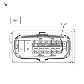
- CHECK HARNESS AND CONNECTOR (+BI TERMINAL)
- Turn the ignition switch off.
*a Front view of wire harness connector
(to No. 1 Skid Control ECU (Brake Booster with Master Cylinder Assembly)) - Make sure that there is no looseness at the locking part and the connecting part of the connector.
OK
The connector is securely connected.
- Disconnect the A44 No. 1 skid control ECU (brake booster with master cylinder assembly) connector.
- Check both the connector case and the terminals for deformation and corrosion.
OK
No deformation or corrosion.
- Measure the voltage according to the value(s) in the table below.
Standard Voltage
Tester Connection Condition Specified Condition A44-14 (+BI1) - Body ground Always 11 to 14 V Result
Proceed to OK NG
Result:
NG
REPAIR OR REPLACE HARNESS OR CONNECTOR
Result:
OK
See step 5
- Turn the ignition switch off.
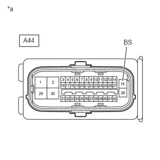
- CHECK HARNESS AND CONNECTOR (BS TERMINAL)
- Measure the voltage according to the value(s) in the table below.
*a Front view of wire harness connector
(to No. 1 Skid Control ECU (Brake Booster with Master Cylinder Assembly))Standard Voltage
Tester Connection Condition Specified Condition A44-15 (BS) - Body ground Always 11 to 14 V Result
Proceed to OK NG
Result:
OK
REPLACE BRAKE BOOSTER WITH MASTER CYLINDER ASSEMBLY. Refer to REMOVAL [11/2023 - ]
Result:
NG
REPAIR OR REPLACE HARNESS OR CONNECTOR
- Measure the voltage according to the value(s) in the table below.