DTC C137B-A2: Brake System Control Module "A" System Voltage System Voltage Low [12/2019 - 10/2021]: Procedure
- READ VALUE USING GTS (IG1 VOLTAGE, IG2 VOLTAGE AND +BS VOLTAGE)
- Using the GTS, monitor the voltage values of IG1 voltage, IG2 voltage, and +BS voltage.
Chassis > Brake/EPB > Data List
Tester Display Measurement Item Range Normal Condition Diagnostic Note IG1 Voltage IG1 voltage value Min.: 0.000 V
Max.: 20.000 V- Changes in proportion to auxiliary battery voltage IG2 Voltage IG2 voltage value Min.: 0.000 V
Max.: 20.000 V- Changes in proportion to auxiliary battery voltage +BS Voltage +BS voltage value Min.: 0.000 V
Max.: 20.000 V- Changes in proportion to auxiliary battery voltage Chassis > Brake/EPB > Data List
Tester Display IG1 Voltage IG2 Voltage +BS Voltage Result
Result Proceed to IG1 voltage value is below 11 V. A IG2 voltage value is below 11 V. B +BS voltage value is below 11 V. C IG1 voltage, IG2 voltage and +BS voltage values are below 11 V. D IG1 voltage, IG2 voltage and +BS voltage values are 11 to 14 V. E
Result:
B
See step 5
Result:
C
See step 6
Result:
D
See step 7
Result:
E
USE SIMULATION METHOD TO CHECK
Refer to HOW TO PROCEED WITH TROUBLESHOOTING [12/2019 - ]
Result:
A
See step 2
- Using the GTS, monitor the voltage values of IG1 voltage, IG2 voltage, and +BS voltage.
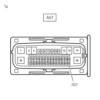
- CHECK HARNESS AND CONNECTOR (IG1 TERMINAL)
- Turn the ignition switch off.
*a Front view of wire harness connector
(to No. 2 Skid Control ECU (Brake Actuator Assembly)) - Make sure that there is no looseness at the locking part and the connecting part of the connectors.
OK
The connector is securely connected.
- Disconnect the A57 No. 2 skid control ECU (brake actuator assembly) connector.
- Check both the connector case and the terminals for deformation and corrosion.
OK
No deformation or corrosion.
- Turn the ignition switch to ON.
- Measure the voltage according to the value(s) in the table below.
Standard Voltage
Tester Connection Condition Specified Condition A57-45 (IG1) - Body ground Ignition switch ON 11 to 14 V Result
Proceed to OK NG
Result:
NG
REPAIR OR REPLACE HARNESS OR CONNECTOR
Result:
OK
See step 3
- Turn the ignition switch off.
- CLEAR DTC
- Reconnect the A57 No. 2 skid control ECU (brake actuator assembly) connector.
- Clear the DTCs.
Chassis > Brake/EPB > Clear DTCs
- Turn the ignition switch off.
Result
Proceed to NEXT
Result:
NEXT
See step 4
- RECONFIRM DTC
- Based on the Freeze Frame Data and interview with the customer, attempt to reproduce the conditions when the malfunction occurred.
- Check if the same DTC is output.
Chassis > Brake/EPB > Trouble Codes
Result
Result Proceed to DTC C137B-A2 is not output. A DTC C137B-A2 is output. B
Result:
A
USE SIMULATION METHOD TO CHECK
Refer to HOW TO PROCEED WITH TROUBLESHOOTING [12/2019 - ]
Result:
B
REPLACE BRAKE ACTUATOR ASSEMBLY
Refer to REMOVAL [12/2019 - 10/2022]
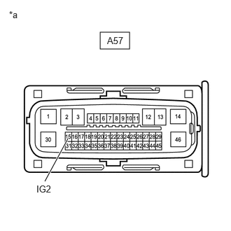
- CHECK HARNESS AND CONNECTOR (IG2 TERMINAL)
- Turn the ignition switch off.
*a Front view of wire harness connector
(to No. 2 Skid Control ECU (Brake Actuator Assembly)) - Make sure that there is no looseness at the locking part and the connecting part of the connectors.
OK
The connector is securely connected.
- Disconnect the A57 No. 2 skid control ECU (brake actuator assembly) connector.
- Check both the connector case and the terminals for deformation and corrosion.
OK
No deformation or corrosion.
- Turn the ignition switch to ON.
- Measure the voltage according to the value(s) in the table below.
Standard Voltage
Tester Connection Condition Specified Condition A57-15 (IG2) - Body ground Ignition switch ON 11 to 14 V Result
Proceed to OK NG
Result:
OK
See step 3
Result:
NG
REPAIR OR REPLACE HARNESS OR CONNECTOR
- Turn the ignition switch off.
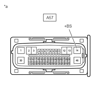
- CHECK HARNESS AND CONNECTOR (+BS TERMINAL)
- Turn the ignition switch off.
*a Front view of wire harness connector
(to No. 2 Skid Control ECU (Brake Actuator Assembly)) - Make sure that there is no looseness at the locking part and the connecting part of the connectors.
OK
The connector is securely connected.
- Disconnect the A57 No. 2 skid control ECU (brake actuator assembly) connector.
- Check both the connector case and the terminals for deformation and corrosion.
OK
No deformation or corrosion.
- Measure the voltage according to the value(s) in the table below.
Standard Voltage
Tester Connection Condition Specified Condition A57-14 (+BS) - Body ground Always 11 to 14 V Result
Proceed to OK NG
Result:
OK
See step 3
Result:
NG
REPAIR OR REPLACE HARNESS OR CONNECTOR
- Turn the ignition switch off.
- CHECK HARNESS AND CONNECTOR (GND1 TERMINAL)
- Turn the ignition switch off.
- Make sure that there is no looseness at the locking part and the connecting part of the connectors.
OK
The connector is securely connected.
- Disconnect the A57 No. 2 skid control ECU (brake actuator assembly) connector.
- Check both the connector case and the terminals for deformation and corrosion.
OK
No deformation or corrosion.
- Measure the resistance according to the value(s) in the table below.
Standard Resistance
Tester Connection Condition Specified Condition A57-1 (GND1) - Body ground 1 minute or more after disconnecting the cable from the negative (-) auxiliary battery terminal Below 1 Ω Result
Proceed to OK NG
Result:
OK
See step 3
Result:
NG
REPAIR OR REPLACE HARNESS OR CONNECTOR