DTC C1380-7E: Stop Lamp Relay Actuator Stuck On [11/2023 - ]: Procedure
- CHECK STOP LIGHT ILLUMINATION STATUS
- With the brake pedal released, check the illumination status of the stop lights.
Result
Result Proceed to The stop lights are illuminated. A The stop lights are not illuminated. B
Result:
B
See step 5
Result:
A
See step 2
- With the brake pedal released, check the illumination status of the stop lights.
- CHECK BRAKE ACTUATOR ASSEMBLY
- Make sure that there is no looseness at the locking part and the connecting part of the connectors.
OK
The connector is securely connected.
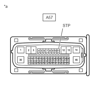
*a Front view of wire harness connector
(to No. 2 Skid Control ECU (Brake Actuator Assembly)) - Disconnect the A57 No. 2 skid control ECU (brake actuator assembly) connector.
- Check both the connector case and the terminals for deformation and corrosion.
OK
No deformation or corrosion.
- Measure the voltage according to the value(s) in the table below.
Standard Voltage
Tester Connection Condition Specified Condition A57-11 (STP) - Body ground Stop light switch assembly off
(Brake pedal released)Below 1.5 V Result
Proceed to OK NG
Result:
OK
REPLACE BRAKE ACTUATOR ASSEMBLY. Refer to REMOVAL [11/2023 - ]
Result:
NG
See step 3
- Make sure that there is no looseness at the locking part and the connecting part of the connectors.
- CHECK STOP LIGHT SWITCH ASSEMBLY
- Make sure that there is no looseness at the locking part and the connecting part of the connectors.
OK
The connector is securely connected.
*a Front view of wire harness connector
(to No. 2 Skid Control ECU (Brake Actuator Assembly)) - Disconnect the A42 stop light switch assembly connector.
- Check both the connector case and the terminals for deformation and corrosion.
OK
No deformation or corrosion.
- Measure the voltage according to the value(s) in the table below.
Standard Voltage
Tester Connection Condition Specified Condition A57-11 (STP) - Body ground Always Below 1.5 V Result
Proceed to OK NG
Result:
OK
REPLACE STOP LIGHT SWITCH ASSEMBLY. Refer to REMOVAL [12/2019 - ]
Result:
NG
See step 4
- Make sure that there is no looseness at the locking part and the connecting part of the connectors.
- CHECK FOR SHORT TO +B IN STP CIRCUIT
- Check that there is no short to +B in the STP circuit (wire harnesses, connectors, stop lights and ECUs).
OK
No short to +B.
Result
Proceed to OK NG
Result:
OK
USE SIMULATION METHOD TO CHECK. Refer to HOW TO PROCEED WITH TROUBLESHOOTING [12/2019 - ]
Result:
NG
REPAIR OR REPLACE MALFUNCTIONING PART
- Check that there is no short to +B in the STP circuit (wire harnesses, connectors, stop lights and ECUs).
- CHECK BRAKE ACTUATOR ASSEMBLY
- Make sure that there is no looseness at the locking part and the connecting part of the connectors.
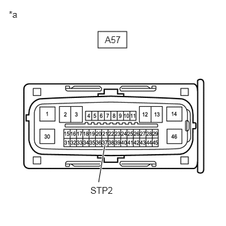
*a Front view of wire harness connector
(to No. 2 Skid Control ECU (Brake Actuator Assembly))OK
The connector is securely connected.
- Disconnect the A57 No. 2 skid control ECU (brake actuator assembly) connector.
- Check both the connector case and the terminals for deformation and corrosion.
OK
No deformation or corrosion.
- Measure the voltage according to the value(s) in the table below.
Standard Voltage
Tester Connection Condition Specified Condition A57-37 (STP2) - Body ground Stop light switch assembly on (Brake pedal depressed) 11 to 14 V Result
Proceed to OK NG
Result:
OK
REPLACE BRAKE ACTUATOR ASSEMBLY. Refer to REMOVAL [11/2023 - ]
Result:
NG
See step 6
- Make sure that there is no looseness at the locking part and the connecting part of the connectors.
- CHECK HARNESS AND CONNECTOR (STOP LIGHT SWITCH ASSEMBLY - BRAKE ACTUATOR ASSEMBLY)
- Make sure that there is no looseness at the locking part and the connecting part of the connector.
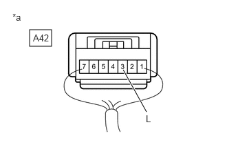
*a Component with harness connected
(Stop Light Switch Assembly)OK
The connector is securely connected.
- Measure the voltage according to the value(s) in the table below.
Standard Voltage
Tester Connection Condition Specified Condition A42-3 (L) - Body ground Stop light switch assembly on (Brake pedal depressed) 11 to 14 V Result
Proceed to OK NG
Result:
OK
REPAIR OR REPLACE HARNESS OR CONNECTOR
Result:
NG
See step 7
- Make sure that there is no looseness at the locking part and the connecting part of the connector.
- CHECK FOR SHORT TO GROUND IN STP2 CIRCUIT
- Check that there is no short to ground in the STP2 circuit (wire harnesses, connectors and ECUs)
OK
There is no short to ground.
Result
Proceed to OK NG
Result:
OK
REPLACE STOP LIGHT SWITCH ASSEMBLY. Refer to REMOVAL [12/2019 - ]
Result:
NG
REPAIR OR REPLACE MALFUNCTIONING PART
- Check that there is no short to ground in the STP2 circuit (wire harnesses, connectors and ECUs)