DTC C1380-7F: Stop Lamp Relay Actuator Stuck Off [11/2023 - ]: Procedure
- PERFORM ACTIVE TEST USING GTS (STOP LAMP RELAY)
- Perform the stop light control relay (stop light switch assembly) Active Test, and confirm that the stop lights illuminate and turn off and the value of "Stop Light SW", "Stop Light Relay" and "STPO" changes.
Chassis > Brake/EPB > Active Test
Tester Display Measurement Item Control Range Restrict Condition Diagnostic Note Stop Lamp Relay Stop light control relay (Stop light switch assembly) OFF / ON Vehicle condition: Vehicle stopped
HINT:
To protect this Actuator and Solenoid, this test will only last 5 seconds.With the brake pedal released, check that the stop lights illuminate and the value of Stop Light Relay on the GTS changes to ON when Stop Lamp Relay is ON Chassis > Brake/EPB > Data List
Tester Display Measurement Item Range Normal Condition Diagnostic Note Stop Light SW Stop light switch assembly status
(STP or STP2 terminal input)OFF / ON OFF: Brake pedal released
ON: Brake pedal depressedHINT: - Stop light control relay off: STP terminal status displayed.
- Stop light control relay on: STP2 terminal status displayed.
Stop Light Relay Stop light control relay (Stop light switch assembly) status
(STP terminal input)OFF / ON OFF: Stop light control relay (Stop light switch assembly) off and brake pedal released
ON: Stop light control relay (Stop light switch assembly) on or brake pedal depressedHINT:
The voltage of power supplied to the stop lights is measured at the STP terminal.STPO Stop light control relay (Stop light switch assembly) status
(STPO terminal output)OFF / ON OFF: Stop light control relay (Stop light switch assembly) off (Stop light off)
ON: Stop light control relay (Stop light switch assembly) on (Stop light on)HINT:
When STPO is ON, the stop light control relay (stop light switch assembly) turns ON and the stop lights illuminateChassis > Brake/EPB > Active Test
Active Test Display Stop Lamp Relay Data List Display Stop Light SW Stop Light Relay STPO Result
Data List Status Stop Light Illumination Status Proceed to Stop Light SW Stop Light Relay STPO OFF OFF ON Not illuminated A OFF OFF ON Illuminated B ON ON ON Illuminated C
Result:
B
See step 7
Result:
C
See step 8
Result:
A
See step 2
- Perform the stop light control relay (stop light switch assembly) Active Test, and confirm that the stop lights illuminate and turn off and the value of "Stop Light SW", "Stop Light Relay" and "STPO" changes.
- CHECK HARNESS AND CONNECTOR (STOP LIGHT SWITCH ASSEMBLY - BRAKE ACTUATOR ASSEMBLY)
- Turn the ignition switch off.
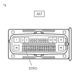
*a Front view of wire harness connector
(to No. 2 Skid Control ECU (Brake Actuator Assembly)) - Make sure that there is no looseness at the locking part and the connecting part of the connectors.
OK
The connector is securely connected.
- Disconnect the A57 No. 2 skid control ECU (brake actuator assembly) connector.
- Check both the connector case and the terminals for deformation and corrosion.
OK
No deformation or corrosion.
- Measure the voltage according to the value(s) in the table below.
Standard Voltage
Tester Connection Condition Specified Condition A57-32 (STPO) - Body ground Always 11 to 14 V Result
Proceed to OK NG
Result:
NG
See step 6
Result:
OK
See step 3
- Turn the ignition switch off.
- CHECK BRAKE ACTUATOR ASSEMBLY
- Measure the voltage according to the value(s) in the table below.
Standard Voltage
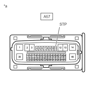
Tester Connection Condition Specified Condition A57-11 (STP) - Body ground Stop light switch assembly on (Brake pedal depressed) 11 to 14 V *a Front view of wire harness connector
(to No. 2 Skid Control ECU (Brake Actuator Assembly))Result
Proceed to OK NG
Result:
OK
REPLACE BRAKE ACTUATOR ASSEMBLY. Refer to REMOVAL [11/2023 - ]
Result:
NG
See step 4
- Measure the voltage according to the value(s) in the table below.
- CHECK FOR SHORT TO GROUND IN STP CIRCUIT
- Check that there is no short to ground in the STP circuit (wire harnesses, connectors, stop lights and ECUs)
OK
There is no short to ground.
Result
Proceed to OK NG
Result:
NG
REPAIR OR REPLACE MALFUNCTIONING PART
Result:
OK
See step 5
- Check that there is no short to ground in the STP circuit (wire harnesses, connectors, stop lights and ECUs)
- CHECK HARNESS AND CONNECTOR (STOP LIGHT SWITCH ASSEMBLY - BRAKE ACTUATOR ASSEMBLY)
- Make sure that there is no looseness at the locking part and the connecting part of the connectors.
OK
The connector is securely connected.
- Disconnect the A42 stop light switch assembly connector.
- Check both the connector case and the terminals for deformation and corrosion.
OK
No deformation or corrosion.
- Measure the resistance according to the value(s) in the table below.
Standard Resistance
Tester Connection Condition Specified Condition A42-1 (OUT) - A57-11 (STP) Always Below 1 Ω Result
Proceed to OK NG
Result:
OK
REPLACE STOP LIGHT SWITCH ASSEMBLY. Refer to REMOVAL [12/2019 - ]
Result:
NG
REPAIR OR REPLACE HARNESS OR CONNECTOR
- Make sure that there is no looseness at the locking part and the connecting part of the connectors.
- CHECK STOP LIGHT SWITCH ASSEMBLY
- Make sure that there is no looseness at the locking part and the connecting part of the connectors.
OK
The connector is securely connected.
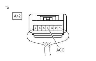
*a Component with harness connected
(Stop Light Switch Assembly) - Measure the voltage according to the value(s) in the table below.
Standard Voltage
Tester Connection Condition Specified Condition A42-4 (ACC) - Body ground Always 11 to 14 V Result
Proceed to OK NG
Result:
OK
REPAIR OR REPLACE HARNESS OR CONNECTOR
Result:
NG
REPLACE STOP LIGHT SWITCH ASSEMBLY. Refer to REMOVAL [12/2019 - ]
- Make sure that there is no looseness at the locking part and the connecting part of the connectors.
- CHECK BRAKE ACTUATOR ASSEMBLY
- Turn the ignition switch off.
*a Front view of wire harness connector
(to No. 2 Skid Control ECU (Brake Actuator Assembly)) - Make sure that there is no looseness at the locking part and the connecting part of the connectors.
OK
The connector is securely connected.
- Disconnect the A57 No. 2 skid control ECU (brake actuator assembly) connector.
- Check both the connector case and the terminals for deformation and corrosion.
OK
No deformation or corrosion.
- Measure the voltage according to the value(s) in the table below.
Standard Voltage
Tester Connection Condition Specified Condition A57-11 (STP) - Body ground Stop light switch assembly on (Brake pedal depressed) 11 to 14 V Result
Proceed to OK NG
Result:
OK
REPLACE BRAKE ACTUATOR ASSEMBLY. Refer to REMOVAL [11/2023 - ]
Result:
NG
REPAIR OR REPLACE HARNESS OR CONNECTOR
- Turn the ignition switch off.
- CHECK BRAKE ACTUATOR ASSEMBLY
- Turn the ignition switch off.
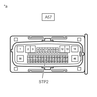
*a Front view of wire harness connector
(to No. 2 Skid Control ECU (Brake Actuator Assembly)) - Make sure that there is no looseness at the locking part and the connecting part of the connectors.
OK
The connector is securely connected.
- Disconnect the A57 No. 2 skid control ECU (brake actuator assembly) connector.
- Check both the connector case and the terminals for deformation and corrosion.
OK
No deformation or corrosion.
- Measure the voltage according to the value(s) in the table below.
Standard Voltage
Tester Connection Condition Specified Condition A57-37 (STP2) - Body ground Stop light switch assembly off
(Brake pedal released)Below 1.5 V Result
Proceed to OK NG
Result:
OK
REPLACE BRAKE ACTUATOR ASSEMBLY. Refer to REMOVAL [11/2023 - ]
Result:
NG
See step 9
- Turn the ignition switch off.
- CHECK STOP LIGHT SWITCH ASSEMBLY
- Make sure that there is no looseness at the locking part and the connecting part of the connectors.
OK
The connector is securely connected.
*a Front view of wire harness connector
(to No. 2 Skid Control ECU (Brake Actuator Assembly)) - Disconnect the A42 stop light switch assembly connector.
- Check both the connector case and the terminals for deformation and corrosion.
OK
No deformation or corrosion.
- Measure the voltage according to the value(s) in the table below.
Standard Voltage
Tester Connection Condition Specified Condition A57-37 (STP2) - Body ground Always Below 1.5 V Result
Proceed to OK NG
Result:
OK
REPLACE STOP LIGHT SWITCH ASSEMBLY. Refer to REMOVAL [12/2019 - ]
Result:
NG
See step 10
- Make sure that there is no looseness at the locking part and the connecting part of the connectors.
- CHECK FOR SHORT TO +B IN STP2 CIRCUIT
- Check that there is no short to +B in the STP2 circuit (wire harnesses, connectors and ECUs).
OK
No short to +B.
Result
Proceed to OK NG
Result:
OK
USE SIMULATION METHOD TO CHECK. Refer to HOW TO PROCEED WITH TROUBLESHOOTING [12/2019 - ]
Result:
NG
REPAIR OR REPLACE MALFUNCTIONING PART
- Check that there is no short to +B in the STP2 circuit (wire harnesses, connectors and ECUs).