DTC C1202-00: Master Reservoir Level Malfunction [10/2021 - 11/2023]: Procedure
- CHECK DTC
- Check the DTCs that are output.
Chassis > Brake Booster > Trouble Codes
Chassis > Brake/EPB > Trouble Codes
Result
Result Proceed to Only DTC C1202-00 is output. A DTCs other than C1202-00 are output. B
Result:
B
REPAIR CIRCUITS INDICATED BY OUTPUT DTCS. Refer to DIAGNOSTIC TROUBLE CODE CHART [10/2021 - 11/2023]
Result:
A
See step 2
- Check the DTCs that are output.
- CHECK BRAKE FLUID LEVEL
- Check that the brake fluid level is sufficient.
HINT:
If the fluid level is low, check for fluid leaks, and repair as necessary.
- Check for brake fluid leaks (connection between the brake booster with accumulator pump assembly, brake master cylinder reservoir assembly, brake booster with master cylinder assembly, brake actuator assembly, and wheel cylinders).
HINT:
If no leaks exist, add and adjust fluid using the GTS.
Refer to ON-VEHICLE INSPECTION [12/2019 - ]
- Check the thickness of the brake pad lining.
for Front Brake: Refer to INSPECTION [12/2019 - ]
for Rear Brake: Refer to INSPECTION [12/2019 - ]
HINT:
If the thickness is less than the standard, replace the brake pads with new ones.
- Check for brake fluid leaks (connection between the brake booster with accumulator pump assembly, brake master cylinder reservoir assembly, brake booster with master cylinder assembly, brake actuator assembly, and wheel cylinders).
- Check that there are no leaks from the connections between the brake booster with accumulator pump assembly, brake booster with master cylinder assembly and brake actuator assembly.
HINT:
As a visual check is very difficult, perform the check with the following procedure.
- Bleed the air from the brake system.
Refer to BLEEDING [12/2019 - ]
- Turn the ignition switch off.
- Disconnect the A43 brake pedal stroke sensor assembly connector.
- Depress the brake pedal several times to operate the pump motor, then wait until it stops.
- After the pump motor stops, wait for 30 seconds, then check the drop in the accumulator pressure sensor output value and the state of the pump motor.
Chassis > Brake Booster > Data List
Tester Display Measurement Item Range Normal Condition Diagnostic Note ECB Motor Relay Motor relay operation request OFF / ON OFF: Relay off
ON: Relay onECB: Electronically Controlled Brake System Accumulator Pressure Accumulator pressure output value Min.: 0.00 MPa
Max.: 24.48 MPa15.00 to 21.00 MPa (Pressure stable and pump motor stopped) When brake fluid is stored in the accumulator: Accumulator pressure changes in accordance with volume of fluid stored in the accumulator Chassis > Brake Booster > Data List
Tester Display ECB Motor Relay Accumulator Pressure
Result
Result Proceed to The drop in the accumulator pressure sensor output value is less than 2.50 MPa 30 seconds after the pump motor stops, and the pump motor does not operate within 30 seconds after the pump motor stops. A The drop in the accumulator pressure sensor output value is 2.50 MPa or more 30 seconds after the pump motor stops, or the pump motor operates within 30 seconds after the pump motor stops. B - Bleed the air from the brake system.
Result:
B
CHECK AND REPAIR BRAKE FLUID LEAKS OR ADD FLUID
Result:
A
See step 3
- Check that the brake fluid level is sufficient.
- INSPECT BRAKE MASTER CYLINDER RESERVOIR ASSEMBLY
- Turn the ignition switch off.
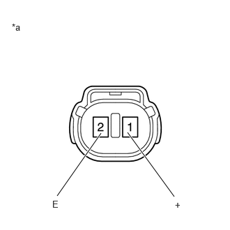
*a Component without harness connected
(Brake Fluid Level Warning Switch (Brake Master Cylinder Reservoir Assembly)) - Reconnect the A43 brake pedal stroke sensor assembly connector.
- Remove the brake master cylinder reservoir filler cap assembly.
- Make sure that there is no looseness at the locking part and the connecting part of the connector.
OK
The connector is securely connected.
- Disconnect the A5 brake fluid level warning switch (brake master cylinder reservoir assembly) connector.
- Check both the connector case and the terminals for deformation and corrosion.
OK
No deformation or corrosion.
- Measure the resistance according to the value(s) in the table below.
HINT:
A float is located inside the brake master cylinder reservoir assembly. Its position changes according to the level of brake fluid.
Standard Resistance
Tester Connection Condition Specified Condition 1 (+) - 2 (E) Brake fluid level warning switch (brake master cylinder reservoir assembly) off (float up) 1.84 to 2.16 kΩ 1 (+) - 2 (E) Brake fluid level warning switch (brake master cylinder reservoir assembly) on (float down) Below 1 Ω
(Brake fluid level is low) - If there are no problems after completing the preceding inspection, adjust the brake fluid to the MAX level with the ignition switch turned to ON.
Result
Proceed to OK NG
Result:
NG
REPLACE BRAKE MASTER CYLINDER RESERVOIR ASSEMBLY
Result:
OK
See step 4
- Turn the ignition switch off.
- CHECK HARNESS AND CONNECTOR (BRAKE BOOSTER WITH MASTER CYLINDER ASSEMBLY - BRAKE MASTER CYLINDER RESERVOIR ASSEMBLY)
- Turn the ignition switch off.
- Make sure that there is no looseness at the locking part and the connecting part of the connector.
OK
The connector is securely connected.
- Disconnect the A44 No. 1 skid control ECU (brake booster with master cylinder assembly) connector.
- Check both the connector case and the terminals for deformation and corrosion.
OK
No deformation or corrosion.
- Measure the resistance according to the value(s) in the table below.
Standard Resistance
Tester Connection Condition Specified Condition A44-12 (LBL) - A5-1 (+) Always Below 1 Ω A44-12 (LBL) or A5-1 (+) - Body ground Always 10 kΩ or higher A5-2 (E) - Body ground 1 minute or more after disconnecting the cable from the negative (-) auxiliary battery terminal Below 1 Ω Result
Proceed to OK NG
Result:
NG
REPAIR OR REPLACE HARNESS OR CONNECTOR
Result:
OK
See step 5
- INSPECT BRAKE BOOSTER WITH MASTER CYLINDER ASSEMBLY (SWITCH INPUT)
- Reconnect the A44 No. 1 skid control ECU (brake booster with master cylinder assembly) connector.
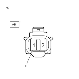
*a Front view of wire harness connector
(to Brake Fluid Level Warning Switch (Brake Master Cylinder Reservoir Assembly)) - Turn the ignition switch to ON.
- Measure the voltage according to the value(s) in the table below.
Standard Voltage
Tester Connection Condition Specified Condition A5-1 (+) - Body ground Ignition switch ON 11 to 14 V Result
Proceed to OK NG
Result:
NG
REPLACE BRAKE BOOSTER WITH MASTER CYLINDER ASSEMBLY. Refer to REMOVAL [12/2019 - 10/2022] , or refer to REMOVAL [10/2022 - 11/2023]
Result:
OK
See step 6
- Reconnect the A44 No. 1 skid control ECU (brake booster with master cylinder assembly) connector.
- CLEAR DTC
- Turn the ignition switch off.
- Reconnect the A5 brake fluid level warning switch (brake master cylinder reservoir assembly) connector.
- Clear the DTCs.
Chassis > Brake Booster > Clear DTCs
- Turn the ignition switch off.
Result
Proceed to NEXT
Result:
NEXT
See step 7
- RECONFIRM DTC
- Based on the Freeze Frame Data and interview with the customer, attempt to reproduce the conditions when the malfunction occurred.
- Check if the same DTC is output.
Chassis > Brake Booster > Trouble Codes
Result
Result Proceed to DTC C1202-00 is not output. A DTC C1202-00 is output. B
Result:
A
USE SIMULATION METHOD TO CHECK. Refer to HOW TO PROCEED WITH TROUBLESHOOTING [12/2019 - ]
Result:
B
REPLACE BRAKE BOOSTER WITH MASTER CYLINDER ASSEMBLY. Refer to REMOVAL [12/2019 - 10/2022] , or refer to REMOVAL [10/2022 - 11/2023]