DTC C05C1-00: Brake Pedal Position Sensor "B" [12/2019 - 11/2023]: Procedure
- CHECK BRAKE PEDAL
- Check that the brake pedal and the brake pedal stroke sensor assembly are properly installed and that the pedal can be depressed normally.
- Check and adjust the brake pedal height.
Refer to ADJUSTMENT [12/2019 - 10/2022] , or refer to ADJUSTMENT [10/2022 - ]
- Adjust the brake pedal stroke sensor assembly.
Refer to INSTALLATION [12/2019 - 11/2023]
Result
Proceed to NEXT
Result:
NEXT
See step 2
- PERFORM BRAKE PEDAL STROKE SENSOR ASSEMBLY ZERO POINT CALIBRATION
- Perform brake pedal stroke sensor assembly zero point calibration.
Refer to UTILITY [12/2019 - 11/2023]
Chassis > Brake/EPB > Utility
Tester Display Reset Memory Chassis > Brake/EPB > Utility
Tester Display Calibration Result
Proceed to NEXT
Result:
NEXT
See step 3
- Perform brake pedal stroke sensor assembly zero point calibration.
- CLEAR DTC
- Clear the DTCs.
Chassis > Brake Booster > Clear DTCs
Chassis > Brake/EPB > Clear DTCs
- Turn the ignition switch off.
Result
Proceed to NEXT
Result:
NEXT
See step 4
- Clear the DTCs.
- RECONFIRM DTC
- Based on the Freeze Frame Data and interview with the customer, attempt to reproduce the conditions when the malfunction occurred.
- Check if the same DTC is output.
Chassis > Brake Booster > Trouble Codes
Chassis > Brake/EPB > Trouble Codes
Result
Result Proceed to Only DTC C05C1-00 is output. A DTCs are not output. B DTCs other than C05C1-00 are output. C
Result:
B
END
Result:
C
REPAIR CIRCUITS INDICATED BY OUTPUT DTCS. Refer to DIAGNOSTIC TROUBLE CODE CHART [12/2019 - 10/2021] , or refer to DIAGNOSTIC TROUBLE CODE CHART [10/2021 - 11/2023]
Result:
A
See step 5
- INSPECT BRAKE ACTUATOR ASSEMBLY (SENSOR OUTPUT)
- Turn the ignition switch off.
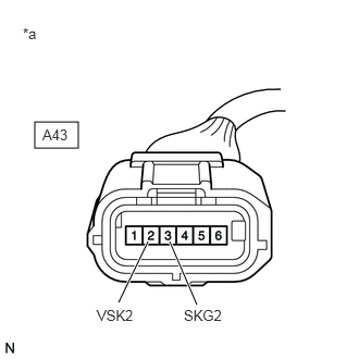
*a Front view of wire harness connector
(to Brake Pedal Stroke Sensor Assembly) - Make sure that there is no looseness at the locking part and the connecting part of the connectors.
OK
The connector is securely connected.
- Disconnect the A43 brake pedal stroke sensor assembly connector.
- Check both the connector case and the terminals for deformation and corrosion.
OK
No deformation or corrosion.
- Turn the ignition switch to ON.
- Measure the voltage according to the value(s) in the table below.
Standard Voltage
Tester Connection Condition Specified Condition A43-2 (VSK2) - A43-3 (SKG2) Ignition switch ON 4.84 to 5.16 V Result
Proceed to OK NG
Result:
OK
REPLACE BRAKE PEDAL STROKE SENSOR ASSEMBLY. Refer to REMOVAL [12/2019 - 10/2022] , or refer to REMOVAL [10/2022 - 11/2023]
Result:
NG
REPAIR OR REPLACE HARNESS OR CONNECTOR
- Turn the ignition switch off.