DTC C1103-1C: Brake Pedal Position Sensor "B" Supply Voltage Circuit Voltage Out of Range [11/2023 - ]: Procedure
WARNING: This page is about a different variant/trim than selected.
- CHECK BRAKE PEDAL
- Check that the brake pedal and the brake pedal stroke sensor assembly are properly installed and that the pedal can be depressed normally.
- Check and adjust the brake pedal height.
Refer to ADJUSTMENT [10/2022 - ]
- Adjust the brake pedal stroke sensor assembly.
Refer to INSTALLATION [11/2023 - ]
Result
Proceed to NEXT
Result:
NEXT
See step 2
- CHECK HARNESS AND CONNECTOR (BRAKE ACTUATOR ASSEMBLY - BRAKE PEDAL STROKE SENSOR ASSEMBLY)
- Turn the ignition switch off.
- Make sure that there is no looseness at the locking part and the connecting part of the connectors.
OK
The connector is securely connected.
- Disconnect the A57 No. 2 skid control ECU (brake actuator assembly) connector.
- Disconnect the A90 brake pedal stroke sensor assembly connector.
- Check both the connector case and the terminals for deformation and corrosion.
OK
No deformation or corrosion.
- Measure the resistance according to the value(s) in the table below.
Standard Resistance
Tester Connection Condition Specified Condition A57-26 (SKG2) - A90-3 (SKG2) Always Below 1 Ω A57-26 (SKG2) or A90-3 (SKG2) - Body ground Always 10 kΩ or higher A57-25 (VSK2) - A90-2 (VSK2) Always Below 1 Ω A57-25 (VSK2) or A90-2 (VSK2) - Body ground Always 10 kΩ or higher Result
Proceed to OK NG
Result:
NG
REPAIR OR REPLACE HARNESS OR CONNECTOR
Result:
OK
See step 3
- INSPECT BRAKE ACTUATOR ASSEMBLY (SENSOR OUTPUT)
- Reconnect the A57 No. 2 skid control ECU (brake actuator assembly) connector.
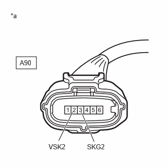
*a Front view of wire harness connector
(to Brake Pedal Stroke Sensor Assembly) - Turn the ignition switch to ON.
- Measure the voltage according to the value(s) in the table below.
Standard Voltage
Tester Connection Condition Specified Condition A90-2 (VSK2) - A90-3 (SKG2) Ignition switch ON 4.84 to 5.16 V Result
Proceed to OK NG
Result:
OK
REPLACE BRAKE PEDAL STROKE SENSOR ASSEMBLY. Refer to REMOVAL [11/2023 - ]
Result:
NG
REPLACE BRAKE ACTUATOR ASSEMBLY. Refer to REMOVAL [11/2023 - ]
- Reconnect the A57 No. 2 skid control ECU (brake actuator assembly) connector.