DTC C110E-14: Brake Booster Motor "A" Supply Voltage Circuit Short to Ground or Open [11/2023 - ]: Procedure
WARNING: This page is about a different variant/trim than selected.
- CHECK DTC
- Check the DTCs that are output.
Chassis > Brake Booster > Trouble Codes
Chassis > Brake/EPB > Trouble Codes
Result
Result Proceed to Only DTC C110E-14 is output. A DTCs other than C110E-14 are output. B
Result:
B
REPAIR CIRCUITS INDICATED BY OUTPUT DTCS. Refer to DIAGNOSTIC TROUBLE CODE CHART [11/2023 - ]
Result:
A
See step 2
- Check the DTCs that are output.
- CHECK HARNESS AND CONNECTOR (+BI1 AND MRI1 TERMINAL)
- Turn the ignition switch off.
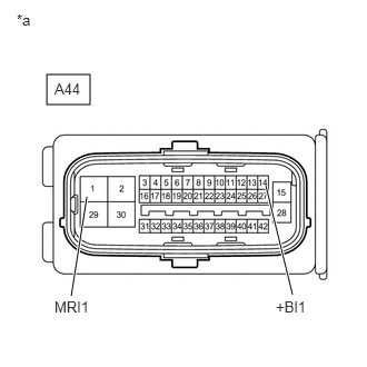
*a Front view of wire harness connector
(to No. 1 Skid Control ECU (Brake Booster with Master Cylinder Assembly)) - Make sure that there is no looseness at the locking part and the connecting part of the connector.
OK
The connector is securely connected.
- Disconnect the A44 No. 1 skid control ECU (brake booster with master cylinder assembly) connector.
- Check both the connector case and the terminals for deformation and corrosion.
OK
No deformation or corrosion.
- Measure the voltage according to the value(s) in the table below.
Standard Voltage
Tester Connection Condition Specified Condition A44-14 (+BI1) - Body ground Always 11 to 14 V A44-1 (MRI1) - Body ground Always 11 to 14 V Result
Result Proceed to 11 to 14 V. A Below 11 V. B
Result:
A
REPLACE BRAKE BOOSTER WITH MASTER CYLINDER ASSEMBLY. Refer to REMOVAL [11/2023 - ]
Result:
B
REPAIR OR REPLACE HARNESS OR CONNECTOR
- Turn the ignition switch off.