DTC C052C-14: ABS Pump Motor Control Circuit Short to Ground or Open; DTC C052C-16: ABS Pump Motor Control Circuit Voltage Below Threshold; DTC C052C-17: ABS Pump Motor Control Circuit Voltage Above Threshold; DTC C052C-29: ABS Pump Motor Control Signal Invalid; DTC C052C-49: ABS Pump Motor Control Internal Electronic Failure; DTC C052F-14: ABS Pump Motor Supply Voltage Circuit Short to Ground or Open [11/2023 - ]: Procedure
WARNING: This page is about a different variant/trim than selected.
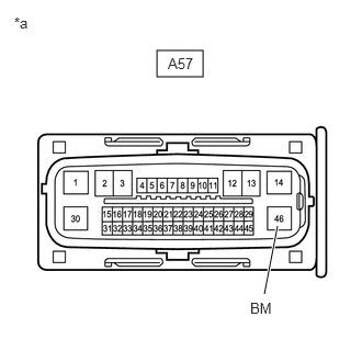
- CHECK HARNESS AND CONNECTOR (BM TERMINAL)
- Make sure that there is no looseness at the locking part and the connecting part of the connectors.
OK
The connector is securely connected.
*a Front view of wire harness connector
(to No. 2 Skid Control ECU (Brake Actuator Assembly)) - Disconnect the A57 No. 2 skid control ECU (brake actuator assembly) connector.
- Check both the connector case and the terminals for deformation and corrosion.
OK
No deformation or corrosion.
- Measure the voltage according to the value(s) in the table below.
Standard Voltage
Tester Connection Condition Specified Condition A57-46 (BM) - Body ground Always 11 to 14 V Result
Proceed to OK NG
Result:
NG
REPAIR OR REPLACE HARNESS OR CONNECTOR
Result:
OK
See step 2
- Make sure that there is no looseness at the locking part and the connecting part of the connectors.
- CHECK HARNESS AND CONNECTOR (GND2 TERMINAL)
- Measure the resistance according to the value(s) in the table below.
Standard Resistance
Tester Connection Condition Specified Condition A57-30 (GND2) - Body ground 1 minute or more after disconnecting the cable from the negative (-) auxiliary battery terminal Below 1 Ω Result
Proceed to OK NG
Result:
NG
REPAIR OR REPLACE HARNESS OR CONNECTOR
Result:
OK
See step 3
- Measure the resistance according to the value(s) in the table below.
- CLEAR DTC
- Reconnect the A57 No. 2 skid control ECU (brake actuator assembly) connector.
- Clear the DTCs.
Chassis > Brake/EPB > Clear DTCs
- Turn the ignition switch off.
Result
Proceed to NEXT
Result:
NEXT
See step 4
- RECONFIRM DTC
- Based on the Freeze Frame Data and interview with the customer, attempt to reproduce the conditions when the malfunction occurred.
- Check if the same DTC is output.
Chassis > Brake/EPB > Trouble Codes
Result
Result Proceed to DTCs C052C-14, C052C-16, C052C-17, C052C-29, C052C-49 and C052F-14 are not output. A DTCs C052C-14, C052C-16, C052C-17, C052C-29, C052C-49 and/or C052F-14 are output. B HINT:
- If a speed signal of 20 km/h (12 mph) or more is sent to the No. 2 skid control ECU (brake actuator assembly) with the ignition switch turned to ON and the stop light switch assembly off, the ECU performs self-diagnosis of the motor circuit.
- If the normal system code is output (no DTCs are output), slightly jiggle the connectors, wire harness, and fuses of the No. 2 skid control ECU (brake actuator assembly).
- If any DTCs are output while jiggling a connector or wire harness of the No. 2 skid control ECU (brake actuator assembly), inspect and repair the connector or wire harness.
- If no DTCs were output when reconfirming DTCs, checking for intermittent problems is necessary because it is suspected that the original DTCs were stored due to the poor connection of a connector terminal.
Result:
A
USE SIMULATION METHOD TO CHECK. Refer to HOW TO PROCEED WITH TROUBLESHOOTING [12/2019 - ]
Result:
B
REPLACE BRAKE ACTUATOR ASSEMBLY. Refer to REMOVAL [11/2023 - ]