DTC C0512-14: Right Rear Wheel Speed Sensor Circuit Short to Ground or Open [10/2021 - 10/2022]: Procedure
- READ VALUE USING GTS (MOMENTARY INTERRUPTION)
- Select the line graph display on the GTS.
- Check for any momentary interruption in the wire harness and connector.
Refer to DATA LIST / ACTIVE TEST [12/2019 - 11/2023]
Chassis > Brake/EPB > Data List
Tester Display Measurement Item Range Normal Condition Diagnostic Note RR Speed Open Rear speed sensor RH open detection Normal / Under intermittent Normal: Normal
Under intermittent: Momentary interruption- RR Speed Sensor Voltage Open Rear speed sensor RH voltage open detection Normal / Under intermittent Normal: Normal
Under intermittent: Momentary interruption- Chassis > Brake/EPB > Data List
Tester Display RR Speed Open RR Speed Sensor Voltage Open OK
Normal (There are no momentary interruptions.)
NOTE:Perform the above inspection before removing the sensor and connector.
Result
Proceed to OK NG
Result:
OK
USE SIMULATION METHOD TO CHECK. Refer to HOW TO PROCEED WITH TROUBLESHOOTING [12/2019 - ]
Result:
NG
See step 2
- CHECK VEHICLE SPECIFICATION
Result:
B
See step 6
Result:
A
See step 3
- INSPECT NO. 1 PARKING BRAKE WIRE ASSEMBLY
- Turn the ignition switch off.
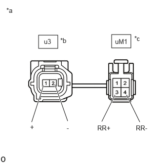
*a Front view of skid control sensor wire RH (No. 1 parking brake wire assembly) *b to Sensor Side Connector *c to Vehicle Side Connector - Make sure that there is no looseness at the locking part and the connecting part of the connectors.
OK
The connector is securely connected.
- Disconnect the u3 and uM1 skid control sensor wire RH (No. 1 parking brake wire assembly) connector.
- Check both the connector case and the terminals for deformation and corrosion.
OK
No deformation or corrosion.
- Measure the resistance according to the value(s) in the table below.
Standard Resistance
Tester Connection Condition Specified Condition u3-1 (+) - uM1-3 (RR+) Always Below 1 Ω u3-1 (+) or uM1-3 (RR+) - Body ground and other terminals Always 10 kΩ or higher u3-2 (-) - uM1-4 (RR-) Always Below 1 Ω u3-2 (-) or uM1-4 (RR-) - Body ground and other terminals Always 10 kΩ or higher Result
Proceed to OK NG
Result:
NG
REPLACE NO. 1 PARKING BRAKE WIRE ASSEMBLY
Result:
OK
See step 4
- Turn the ignition switch off.
- CHECK HARNESS AND CONNECTOR (NO. 1 PARKING BRAKE WIRE ASSEMBLY - BRAKE ACTUATOR ASSEMBLY)
- Make sure that there is no looseness at the locking part and the connecting part of the connectors.
OK
The connector is securely connected.
- Disconnect the A57 No. 2 skid control ECU (brake actuator assembly) connector.
- Check both the connector case and the terminals for deformation and corrosion.
OK
No deformation or corrosion.
- Measure the resistance according to the value(s) in the table below.
Standard Resistance
Tester Connection Condition Specified Condition uM1-3 (RR+) - A57-20 (RR+) Always Below 1 Ω uM1-3 (RR+) or A57-20 (RR+) - Body ground Always 10 kΩ or higher uM1-4 (RR-) - A57-19 (RR-) Always Below 1 Ω uM1-4 (RR-) or A57-19 (RR-) - Body ground Always 10 kΩ or higher Result
Proceed to OK NG
Result:
NG
REPAIR OR REPLACE HARNESS OR CONNECTOR
Result:
OK
See step 5
- Make sure that there is no looseness at the locking part and the connecting part of the connectors.
- INSPECT BRAKE ACTUATOR ASSEMBLY (SENSOR POWER SOURCE CIRCUIT)
- Reconnect the A57 No. 2 skid control ECU (brake actuator assembly) connector.
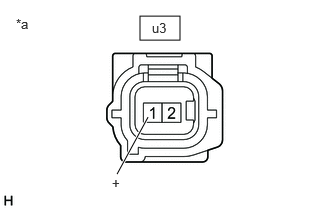
*a Front view of skid control sensor wire RH (No. 1 parking brake wire assembly)
(to Rear Skid Control Sensor RH) - Reconnect the uM1 skid control sensor wire RH (No. 1 parking brake wire assembly) connector.
- Turn the ignition switch to ON.
- Measure the voltage according to the value(s) in the table below.
Standard Voltage
Tester Connection Condition Specified Condition u3-1 (+) - Body ground Ignition switch ON 11 to 14 V Result
Proceed to OK NG
Result:
OK
REPLACE REAR SKID CONTROL SENSOR RH. Refer to REMOVAL [12/2019 - ]
Result:
NG
REPLACE BRAKE ACTUATOR ASSEMBLY. Refer to REMOVAL [12/2019 - 10/2022]
- Reconnect the A57 No. 2 skid control ECU (brake actuator assembly) connector.
- INSPECT NO. 1 PARKING BRAKE WIRE ASSEMBLY
- Turn the ignition switch off.
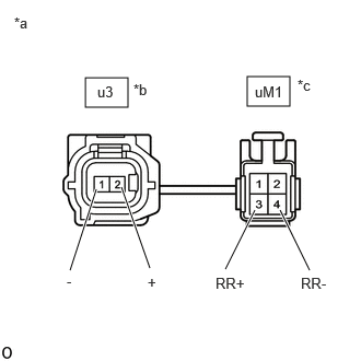
*a Front view of skid control sensor wire RH (No. 1 parking brake wire assembly) *b to Sensor Side Connector *c to Vehicle Side Connector - Make sure that there is no looseness at the locking part and the connecting part of the connectors.
OK
The connector is securely connected.
- Disconnect the u3 and uM1 skid control sensor wire RH (No. 1 parking brake wire assembly) connector.
- Check both the connector case and the terminals for deformation and corrosion.
OK
No deformation or corrosion.
- Measure the resistance according to the value(s) in the table below.
Standard Resistance
Tester Connection Condition Specified Condition u3-2 (+) - uM1-3 (RR+) Always Below 1 Ω u3-2 (+) or uM1-3 (RR+) - Body ground and other terminals Always 10 kΩ or higher u3-1 (-) - uM1-4 (RR-) Always Below 1 Ω u3-1 (-) or uM1-4 (RR-) - Body ground and other terminals Always 10 kΩ or higher Result
Proceed to OK NG
Result:
NG
REPLACE NO. 1 PARKING BRAKE WIRE ASSEMBLY
Result:
OK
See step 7
- Turn the ignition switch off.
- CHECK HARNESS AND CONNECTOR (NO. 1 PARKING BRAKE WIRE ASSEMBLY - BRAKE ACTUATOR ASSEMBLY)
- Make sure that there is no looseness at the locking part and the connecting part of the connectors.
OK
The connector is securely connected.
- Disconnect the A57 No. 2 skid control ECU (brake actuator assembly) connector.
- Check both the connector case and the terminals for deformation and corrosion.
OK
No deformation or corrosion.
- Measure the resistance according to the value(s) in the table below.
Standard Resistance
Tester Connection Condition Specified Condition uM1-3 (RR+) - A57-20 (RR+) Always Below 1 Ω uM1-3 (RR+) or A57-20 (RR+) - Body ground Always 10 kΩ or higher uM1-4 (RR-) - A57-19 (RR-) Always Below 1 Ω uM1-4 (RR-) or A57-19 (RR-) - Body ground Always 10 kΩ or higher Result
Proceed to OK NG
Result:
NG
REPAIR OR REPLACE HARNESS OR CONNECTOR
Result:
OK
See step 8
- Make sure that there is no looseness at the locking part and the connecting part of the connectors.
- INSPECT BRAKE ACTUATOR ASSEMBLY (SENSOR POWER SOURCE CIRCUIT)
- Reconnect the A57 No. 2 skid control ECU (brake actuator assembly) connector.
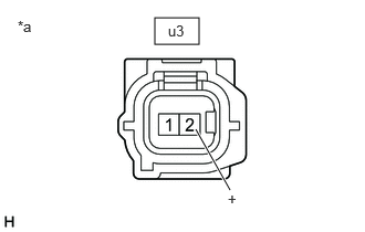
*a Front view of skid control sensor wire RH (No. 1 parking brake wire assembly)
(to Rear Speed Sensor RH (Rear Axle Hub and Bearing Assembly RH)) - Reconnect the uM1 skid control sensor wire RH (No. 1 parking brake wire assembly) connector.
- Turn the ignition switch to ON.
- Measure the voltage according to the value(s) in the table below.
Standard Voltage
Tester Connection Condition Specified Condition u3-2 (+) - Body ground Ignition switch ON 11 to 14 V HINT:
The rear speed sensor RH and rear speed sensor rotor RH are incorporated into the rear axle hub and bearing assembly RH.
If the rear speed sensor RH and rear speed sensor rotor RH need to be replaced, replace the rear axle hub and bearing assembly RH.
Result
Proceed to OK NG
Result:
OK
REPLACE REAR AXLE HUB AND BEARING ASSEMBLY RH. Refer to REMOVAL [12/2019 - 10/2022]
Result:
NG
REPLACE BRAKE ACTUATOR ASSEMBLY. Refer to REMOVAL [12/2019 - 10/2022]
- Reconnect the A57 No. 2 skid control ECU (brake actuator assembly) connector.