DTC C1683: Side Camera Feedback Malfunction [12/2019 - 10/2022]: Procedure
- CHECK FOR DTC
- Clear the DTCs.
Chassis > Circumference Monitoring Camera Control Module > Clear DTCs
- Check for DTCs.
Chassis > Circumference Monitoring Camera Control Module > Trouble Codes
OK
DTC C1683 is not output.
Result
Proceed to OK NG
Result:
OK
USE SIMULATION METHOD TO CHECK. Refer to HOW TO PROCEED WITH TROUBLESHOOTING [12/2019 - ]
Result:
NG
See step 2
- Clear the DTCs.
- CHECK HARNESS AND CONNECTOR (PARKING ASSIST ECU - OUTER REAR VIEW MIRROR ASSEMBLY RH)
- Disconnect the H19 parking assist ECU connector.
- Disconnect the J13 outer rear view mirror assembly RH connector.
- Measure the resistance according to the value(s) in the table below.
Standard Resistance
Tester Connection Condition Specified Condition H19-40 (RCB+) - J13-3 (RCB+) Always Below 1 Ω H19-38 (RCV+) - J13-5 (RCV+) Always Below 1 Ω H19-16 (RCV-) - J13-4 (RCV-) Always Below 1 Ω H19-17 (RGND) - J13-2 (RGND) Always Below 1 Ω H19-39 (SGND) - J13-1 (SGND) Always Below 1 Ω H19-40 (RCB+) or J13-3 (RCB+) - Body ground Always 10 kΩ or higher H19-38 (RCV+) or J13-5 (RCV+) - Body ground Always 10 kΩ or higher H19-16 (RCV-) or J13-4 (RCV-) - Body ground Always 10 kΩ or higher H19-17 (RGND) or J13-2 (RGND) - Body ground Always 10 kΩ or higher H19-39 (SGND) or J13-1 (SGND) - Body ground Always 10 kΩ or higher Result
Proceed to OK NG
Result:
NG
REPAIR OR REPLACE HARNESS OR CONNECTOR
Result:
OK
See step 3
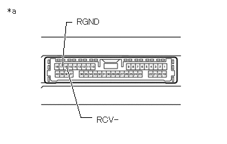
- CHECK PARKING ASSIST ECU (RCV-, RGND)
- Disconnect the H19 parking assist ECU connector.
- Measure the resistance according to the value(s) in the table below.
*a Component without harness connected
(Parking Assist ECU)Standard Resistance
Tester Connection Condition Specified Condition 17 (RGND) - Body ground Always Below 1 Ω 16 (RCV-) - Body ground Always Below 1 Ω Result
Proceed to OK NG
Result:
NG
REPLACE PARKING ASSIST ECU. Refer to REMOVAL [12/2019 - 10/2022]
Result:
OK
See step 4
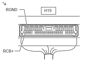
- CHECK PARKING ASSIST ECU (RCB+, RGND)
- Remove the parking assist ECU with the connector still connected.
*a Component with harness connected
(Parking Assist ECU) - Measure the resistance according to the value(s) in the table below.
Standard Resistance
Tester Connection Condition Specified Condition H19-17 (RGND) - Body ground Always Below 1 Ω - Measure the voltage according to the value(s) in the table below.
Standard Voltage
Tester Connection Condition Specified Condition H19-40 (RCB+) - H19-17 (RGND) Ignition switch ON 5.5 to 7.05 V Result
Proceed to OK NG
Result:
NG
REPLACE PARKING ASSIST ECU. Refer to REMOVAL [12/2019 - 10/2022]
Result:
OK
See step 5
- Remove the parking assist ECU with the connector still connected.
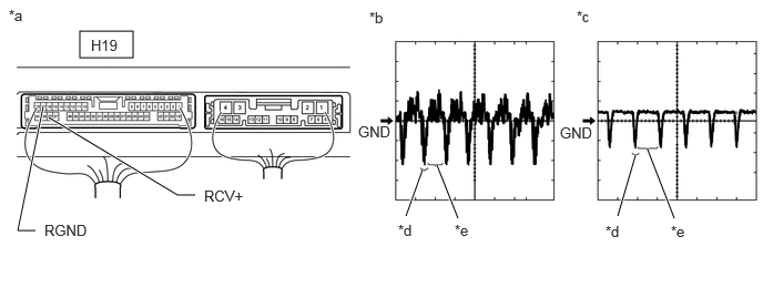
- CHECK SIDE TELEVISION CAMERA ASSEMBLY RH (RCV+, RGND)
- Remove the parking assist ECU with the connector still connected.
- Using an oscilloscope, check the waveform of the side television camera assembly RH.
HINT:
A waterproof connector is used for the side television camera assembly RH. Therefore, inspect the waveform at the parking assist ECU with the connector connected.
*a Component with harness connected
(Parking Assist ECU)*b Waveform 1 (camera lens not covered, displaying an image) *c Waveform 2 (camera lens covered, blacking out the screen) *d Synchronization Signal *e Video Waveform - - HINT:
- The video waveform changes according to the image sent by the side television camera assembly RH.
- The video waveform is constantly output when the ignition switch is turned to ACC.
MEASUREMENT CONDITIONItem Content Tester Connection H19-38 (RCV+) - H19-17 (RGND) Tool Setting 200 mV/DIV., 50 μsec./DIV. Condition Ignition switch ON, panoramic view monitor system operating OK
Waveform is similar to that shown in illustration.
Result
Proceed to OK NG
Result:
OK
REPLACE PARKING ASSIST ECU. Refer to REMOVAL [12/2019 - 10/2022]
Result:
NG
See step 6
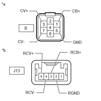
- INSPECT OUTER REAR VIEW MIRROR ASSEMBLY RH
- Disconnect the side television camera assembly RH connector.
*a Front view of wire harness connector
(to Side Television Camera Assembly RH)*b Front view of wire harness connector
(to Outer Rear View Mirror Assembly RH) - Disconnect the outer rear view mirror assembly RH connector.
- Measure the resistance according to the value(s) in the table below.
Standard Resistance
Tester Connection Condition Specified Condition B-1 (CB+) - J13-3 (RCB+) Always Below 1 Ω B-3 (CV+) - J13-5 (RCV+) Always Below 1 Ω B-7 (CV-) - J13-4 (RCV-) Always Below 1 Ω B-5 (GND) - J13-2 (RGND) Always Below 1 Ω B-1 (CB+) or J13-3 (RCB+) - Body ground Always 10 kΩ or higher B-3 (CV+) or J13-5 (RCV+) - Body ground Always 10 kΩ or higher B-7 (CV-) or J13-4 (RCV-) - Body ground Always 10 kΩ or higher B-5 (GND) or J13-2 (RGND) - Body ground Always 10 kΩ or higher Result
Proceed to OK NG
Result:
NG
REPLACE OUTER REAR VIEW MIRROR ASSEMBLY RH. Refer to REMOVAL [12/2019 - 11/2023]
Result:
OK
See step 7
- Disconnect the side television camera assembly RH connector.
- REPLACE SIDE TELEVISION CAMERA ASSEMBLY RH
- Replace the side television camera assembly RH with a new or normally functioning one.
Refer to REMOVAL [12/2019 - 10/2022]
Result
Proceed to NEXT
Result:
NEXT
See step 8
- Replace the side television camera assembly RH with a new or normally functioning one.
- CHECK FOR DTC
- Clear the DTCs.
Chassis > Circumference Monitoring Camera Control Module > Clear DTCs
- Check for DTCs.
Chassis > Circumference Monitoring Camera Control Module > Trouble Codes
OK
DTC C1683 is not output.
Result
Proceed to OK NG
Result:
OK
END (SIDE TELEVISION CAMERA ASSEMBLY RH WAS DEFECTIVE)
Result:
NG
REPLACE PARKING ASSIST ECU. Refer to REMOVAL [12/2019 - 10/2022]
- Clear the DTCs.