DTC C1687: Over Current Detected in Driver Side Camera [12/2019 - 10/2022]: Procedure
- CHECK FOR DTC
- Clear the DTCs.
Chassis > Circumference Monitoring Camera Control Module > Clear DTCs
- Check for DTCs.
Chassis > Circumference Monitoring Camera Control Module > Trouble Codes
OK
DTC C1687 is not output.
Result
Proceed to OK NG
Result:
OK
USE SIMULATION METHOD TO CHECK. Refer to HOW TO PROCEED WITH TROUBLESHOOTING [12/2019 - ]
Result:
NG
See step 2
- Clear the DTCs.
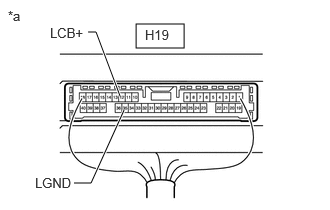
- CHECK HARNESS AND CONNECTOR (PARKING ASSIST ECU - OUTER REAR VIEW MIRROR ASSEMBLY LHRA ASSEMBLY LH)
- Disconnect the H19 parking assist ECU connector.
- Disconnect the J29 outer rear view mirror assembly LH connector.
- Measure the resistance according to the value(s) in the table below.
Standard Resistance
Tester Connection Condition Specified Condition H19-12 (LCB+) - J29-3 (LCB+) Always Below 1 Ω H19-35 (LGND) - J29-2 (LGND) Always Below 1 Ω H19-12 (LCB+) or J29-3 (LCB+) - Body ground Always 10 kΩ or higher H19-35 (LGND) or J29-2 (LGND) - Body ground Always 10 kΩ or higher Result
Proceed to OK NG
Result:
NG
REPAIR OR REPLACE HARNESS OR CONNECTOR
Result:
OK
See step 3
- CHECK PARKING ASSIST ECU (LCB+, LGND)
- Remove the parking assist ECU with the connector still connected.
*a Component with harness connected
(Parking Assist ECU) - Measure the resistance according to the value(s) in the table below.
Standard Resistance
Tester Connection Condition Specified Condition H19-35 (LGND) - Body ground Always Below 1 Ω - Measure the voltage according to the value(s) in the table below.
Standard Voltage
Tester Connection Condition Specified Condition H19-12 (LCB+) - H19-35 (LGND) Ignition switch ON 5.5 to 7.05 V H19-12 (LCB+) - H19-35 (LGND) Ignition switch off Below 1 V Result
Proceed to OK NG
Result:
NG
REPLACE PARKING ASSIST ECU. Refer to REMOVAL [12/2019 - 10/2022]
Result:
OK
See step 4
- Remove the parking assist ECU with the connector still connected.
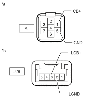
- INSPECT OUTER REAR VIEW MIRROR ASSEMBLY LH
- Disconnect the side television camera assembly LH connector.
*a Front view of wire harness connector
(to Side Television Camera Assembly LH)*b Front view of wire harness connector
(to Outer Rear View Mirror Assembly LH) - Disconnect the outer rear view mirror assembly LH connector.
- Measure the resistance according to the value(s) in the table below.
Standard Resistance
Tester Connection Condition Specified Condition A-1 (CB+) - J29-3 (LCB+) Always Below 1 Ω A-5 (GND) - J29-2 (LGND) Always Below 1 Ω A-1 (CB+) or J29-3 (LCB+) - Body ground Always 10 kΩ or higher A-5 (GND) or J29-2 (LGND) - Body ground Always 10 kΩ or higher Result
Proceed to OK NG
Result:
NG
REPLACE OUTER REAR VIEW MIRROR ASSEMBLY LH. Refer to REMOVAL [12/2019 - 11/2023]
Result:
OK
See step 5
- Disconnect the side television camera assembly LH connector.
- CHECK SIDE TELEVISION CAMERA ASSEMBLY LH
- Replace the side television camera assembly LH with a new or normally functioning one.
Refer to REMOVAL [12/2019 - 10/2022]
Result
Proceed to NEXT
Result:
NEXT
See step 6
- Replace the side television camera assembly LH with a new or normally functioning one.
- CHECK FOR DTC
- Clear the DTCs.
Chassis > Circumference Monitoring Camera Control Module > Clear DTCs
- Check for DTCs.
Chassis > Circumference Monitoring Camera Control Module > Trouble Codes
OK
DTC C1687 is not output.
Result
Proceed to OK NG
Result:
OK
END (SIDE TELEVISION CAMERA ASSEMBLY LH IS DEFECTIVE)
Result:
NG
REPLACE PARKING ASSIST ECU. Refer to REMOVAL [12/2019 - 10/2022]
- Clear the DTCs.