DTC C050C-12: Left Rear Wheel Speed Sensor Circuit Short to Battery [10/2022 - 11/2023]: Procedure
- CHECK VEHICLE SPECIFICATION
Result:
B
See step 6
Result:
A
See step 2
- CHECK HARNESS AND CONNECTOR (SENSOR GROUND CIRCUIT)
- Make sure that there is no looseness at the locking part and the connecting part of the connectors.
OK
The connector is securely connected.
- Disconnect the u4 rear skid control sensor LH connector.
- Check both the connector case and the terminals for deformation and corrosion.
OK
No deformation or corrosion.
- Turn the ignition switch to ON.
- Measure the voltage according to the value(s) in the table below.
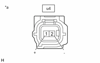
*a Front view of skid control sensor wire LH (No. 2 parking brake wire assembly)
(to Rear Skid Control Sensor LH)Standard Voltage
Tester Connection Condition Specified Condition u4-1 (+) - u4-2 (-) Ignition switch ON 11 to 14 V Result
Proceed to OK NG
Result:
OK
REPLACE REAR SKID CONTROL SENSOR LH. Refer to REMOVAL [12/2019 - ]
Result:
NG
See step 3
- Make sure that there is no looseness at the locking part and the connecting part of the connectors.
- CHECK HARNESS AND CONNECTOR (SENSOR GROUND CIRCUIT)
- Turn the ignition switch off.
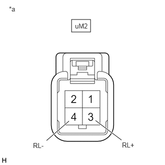
*a Front view of wire harness connector
(to Skid Control Sensor Wire LH (No. 2 Parking Brake Wire Assembly)) - Make sure that there is no looseness at the locking part and the connecting part of the connectors.
OK
The connector is securely connected.
- Disconnect the uM2 skid control sensor wire LH (No. 2 parking brake wire assembly) connector.
- Check both the connector case and the terminals for deformation and corrosion.
OK
No deformation or corrosion.
- Turn the ignition switch to ON.
- Measure the voltage according to the value(s) in the table below.
Standard Voltage
Tester Connection Condition Specified Condition uM2-3 (RL+) - uM2-4 (RL-) Ignition switch ON 11 to 14 V Result
Proceed to OK NG
Result:
OK
REPLACE NO. 2 PARKING BRAKE WIRE ASSEMBLY
Result:
NG
See step 4
- Turn the ignition switch off.
- CHECK HARNESS AND CONNECTOR (SENSOR GROUND CIRCUIT)
- Turn the ignition switch off.
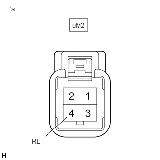
*a Front view of wire harness connector
(to Skid Control Sensor Wire LH (No. 2 Parking Brake Wire Assembly)) - Make sure that there is no looseness at the locking part and the connecting part of the connectors.
OK
The connector is securely connected.
- Disconnect the A57 No. 2 skid control ECU (brake actuator assembly) connector.
- Check both the connector case and the terminals for deformation and corrosion.
OK
No deformation or corrosion.
- Measure the voltage according to the value(s) in the table below.
Standard Voltage
Tester Connection Condition Specified Condition uM2-4 (RL-) - Body ground Always Below 1.5 V Result
Proceed to OK NG
Result:
NG
REPAIR OR REPLACE HARNESS OR CONNECTOR
Result:
OK
See step 5
- Turn the ignition switch off.
- CHECK HARNESS AND CONNECTOR (NO. 2 PARKING BRAKE WIRE ASSEMBLY - BRAKE ACTUATOR ASSEMBLY)
- Measure the resistance according to the value(s) in the table below.
Standard Resistance
Tester Connection Condition Specified Condition uM2-3 (RL+) or A57-5 (RL+) - uM2-4 (RL-) or A57-4 (RL-) Always 10 kΩ or higher Result
Proceed to OK NG
Result:
OK
REPLACE BRAKE ACTUATOR ASSEMBLY. Refer to REMOVAL [10/2022 - 11/2023]
Result:
NG
REPAIR OR REPLACE HARNESS OR CONNECTOR
- Measure the resistance according to the value(s) in the table below.
- CHECK HARNESS AND CONNECTOR (SENSOR GROUND CIRCUIT)
- Make sure that there is no looseness at the locking part and the connecting part of the connectors.
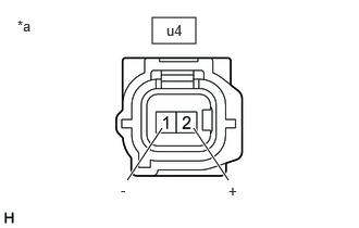
*a Front view of skid control sensor wire LH (No. 2 parking brake wire assembly)
(to Rear Speed Sensor LH (Rear Axle Hub and Bearing Assembly LH))OK
The connector is securely connected.
- Disconnect the u4 rear speed sensor LH (rear axle hub and bearing assembly LH) connector.
- Check both the connector case and the terminals for deformation and corrosion.
OK
No deformation or corrosion.
- Turn the ignition switch to ON.
- Measure the voltage according to the value(s) in the table below.
Standard Voltage
Tester Connection Condition Specified Condition u4-2 (+) - u4-1 (-) Ignition switch ON 11 to 14 V HINT:
The rear speed sensor LH and rear speed sensor rotor LH are incorporated into the rear axle hub and bearing assembly LH.
If the rear speed sensor LH and rear speed sensor rotor LH need to be replaced, replace the rear axle hub and bearing assembly LH.
Result
Proceed to OK NG
Result:
OK
REPLACE REAR AXLE HUB AND BEARING ASSEMBLY LH. Refer to REMOVAL [10/2022 - 11/2023]
Result:
NG
See step 7
- Make sure that there is no looseness at the locking part and the connecting part of the connectors.
- CHECK HARNESS AND CONNECTOR (SENSOR GROUND CIRCUIT)
- Turn the ignition switch off.
*a Front view of wire harness connector
(to Skid Control Sensor Wire LH (No. 2 Parking Brake Wire Assembly)) - Make sure that there is no looseness at the locking part and the connecting part of the connectors.
OK
The connector is securely connected.
- Disconnect the uM2 skid control sensor wire LH (No. 2 parking brake wire assembly) connector.
- Check both the connector case and the terminals for deformation and corrosion.
OK
No deformation or corrosion.
- Turn the ignition switch to ON.
- Measure the voltage according to the value(s) in the table below.
Standard Voltage
Tester Connection Condition Specified Condition uM2-3 (RL+) - uM2-4 (RL-) Ignition switch ON 11 to 14 V Result
Proceed to OK NG
Result:
OK
REPLACE NO. 2 PARKING BRAKE WIRE ASSEMBLY
Result:
NG
See step 8
- Turn the ignition switch off.
- CHECK HARNESS AND CONNECTOR (SENSOR GROUND CIRCUIT)
- Turn the ignition switch off.
*a Front view of wire harness connector
(to Skid Control Sensor Wire LH (No. 2 Parking Brake Wire Assembly)) - Make sure that there is no looseness at the locking part and the connecting part of the connectors.
OK
The connector is securely connected.
- Disconnect the A57 No. 2 skid control ECU (brake actuator assembly) connector.
- Check both the connector case and the terminals for deformation and corrosion.
OK
No deformation or corrosion.
- Measure the voltage according to the value(s) in the table below.
Standard Voltage
Tester Connection Condition Specified Condition uM2-4 (RL-) - Body ground Always Below 1.5 V Result
Proceed to OK NG
Result:
NG
REPAIR OR REPLACE HARNESS OR CONNECTOR
Result:
OK
See step 9
- Turn the ignition switch off.
- CHECK HARNESS AND CONNECTOR (NO. 2 PARKING BRAKE WIRE ASSEMBLY - BRAKE ACTUATOR ASSEMBLY)
- Measure the resistance according to the value(s) in the table below.
Standard Resistance
Tester Connection Condition Specified Condition uM2-3 (RL+) or A57-5 (RL+) - uM2-4 (RL-) or A57-4 (RL-) Always 10 kΩ or higher Result
Proceed to OK NG
Result:
OK
REPLACE BRAKE ACTUATOR ASSEMBLY. Refer to REMOVAL [10/2022 - 11/2023]
Result:
NG
REPAIR OR REPLACE HARNESS OR CONNECTOR
- Measure the resistance according to the value(s) in the table below.