DTC C0506-12: Right Front Wheel Speed Sensor Circuit Short to Battery [11/2023 - ]: Procedure
WARNING: This page is about a different variant/trim than selected.
- CHECK HARNESS AND CONNECTOR (SENSOR GROUND CIRCUIT)
- Make sure that there is no looseness at the locking part and the connecting part of the connectors.
OK
The connector is securely connected.
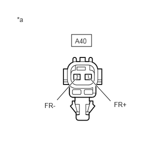
*a Front view of wire harness connector
(to Front Speed Sensor RH) - Disconnect the A40 front speed sensor RH connector.
- Check both the connector case and the terminals for deformation and corrosion.
OK
No deformation or corrosion.
- Turn the ignition switch to ON.
- Measure the voltage according to the value(s) in the table below.
Standard Voltage
Tester Connection Condition Specified Condition A40-1 (FR+) - A40-2 (FR-) Ignition switch ON 11 to 14 V Result
Proceed to OK NG
Result:
OK
REPLACE FRONT SPEED SENSOR RH. Refer to REMOVAL [10/2022 - ]
Result:
NG
See step 2
- Make sure that there is no looseness at the locking part and the connecting part of the connectors.
- CHECK HARNESS AND CONNECTOR (SENSOR GROUND CIRCUIT)
- Turn the ignition switch off.
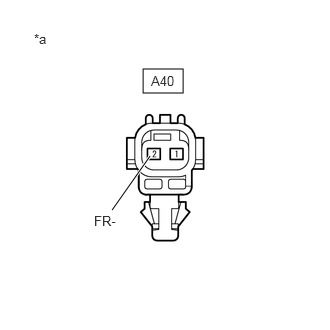
*a Front view of wire harness connector
(to Front Speed Sensor RH) - Make sure that there is no looseness at the locking part and the connecting part of the connectors.
OK
The connector is securely connected.
- Disconnect the A57 No. 2 skid control ECU (brake actuator assembly) connector.
- Check both the connector case and the terminals for deformation and corrosion.
OK
No deformation or corrosion.
- Measure the voltage according to the value(s) in the table below.
Standard Voltage
Tester Connection Condition Specified Condition A40-2 (FR-) - Body ground Always Below 1.5 V Result
Proceed to OK NG
Result:
NG
REPAIR OR REPLACE HARNESS OR CONNECTOR
Result:
OK
See step 3
- Turn the ignition switch off.
- CHECK HARNESS AND CONNECTOR (FRONT SPEED SENSOR RH - BRAKE ACTUATOR ASSEMBLY)
- Measure the resistance according to the value(s) in the table below.
Standard Resistance
Tester Connection Condition Specified Condition A40-1 (FR+) or A57-7 (FR+) - A40-2 (FR-) or A57-6 (FR-) Always 10 kΩ or higher Result
Proceed to OK NG
Result:
OK
REPLACE BRAKE ACTUATOR ASSEMBLY. Refer to REMOVAL [11/2023 - ]
Result:
NG
REPAIR OR REPLACE HARNESS OR CONNECTOR
- Measure the resistance according to the value(s) in the table below.