Installation [12/2019 - ]: Procedure
- INSTALL FRONT FLEXIBLE HOSE NOTE:
When installing the front flexible hose, minimize twisting of the hose.
- Install the front flexible hose with a new clip.
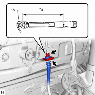
*a Torque Wrench Fulcrum Length *b Union Nut Wrench NOTE:Install the clip as far as it will go.
- Using a union nut wrench, connect the brake line to the front flexible hose while holding the front flexible hose with a wrench.
Specified tightening torque
Torque: 15.2 N.m (155 kgf/cm, 11 ft.lbf)
NOTE:- Do not kink or damage the brake line.
- Do not allow any foreign matter such as dirt or dust to enter the brake line from the connecting parts.
HINT:
- Calculate the torque wrench reading when changing the fulcrum length of the torque wrench.
Refer to PRECAUTION [12/2019 - 11/2023] , or refer to PRECAUTION [11/2023 - ]
- When using a union nut wrench (fulcrum length of 22 mm (0.866 in.)) + torque wrench (fulcrum length of 162 mm (6.38 in.)):
13.4 N.m (137 kgf/cm, 10 ft.lbf)
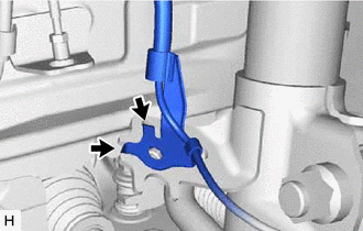
- Engage the 2 hooks to install the front speed sensor clamp bracket.NOTE:
Do not twist the front speed sensor wire harness when installing it.

Hook - Install the front flexible hose and front speed sensor to the front shock absorber assembly with the bolt.
Torque: 29 N.m (296 kgf/cm, 21 ft.lbf)
NOTE:Do not twist the front flexible hose when installing it.
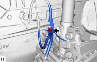
- Connect the front flexible hose to the front disc brake cylinder assembly with a new union bolt and a new gasket.
Torque: 29.4 N.m (300 kgf/cm, 22 ft.lbf)
NOTE:- Install the front flexible hose lock securely into the lock hole in the front disc brake cylinder assembly.
- Do not twist the front flexible hose when installing it.
- Install the front flexible hose with a new clip.
- CONNECT CABLE TO NEGATIVE AUXILIARY BATTERY TERMINAL (for HV Model)
- Connect the reservoir level switch connector.
- Install the brake master cylinder reservoir assembly to the reservoir bracket with the bolt and nut.
Torque: 9.0 N.m (92 kgf/cm, 80 in.lbf)
- Engage the clamp to install the wire harness to the brake master cylinder reservoir assembly.
- Connect the cable to the negative (-) auxiliary battery terminal.
- BLEED BRAKE LINE
for Gasoline Model: Refer to BLEEDING [12/2019 - 10/2022] , or refer to BLEEDING [10/2022 - ]
for HV Model: Refer to BLEEDING [12/2019 - ]
- INSTALL FRONT WHEEL