Caution / Notice / Hint
WARNING: This page is about a different variant/trim than selected.
The necessary procedures (adjustment, calibration, initialization or registration) that must be performed after parts are removed and installed, or replaced during battery voltage sensor removal/installation are shown below.
NECESSARY PROCEDURES AFTER PARTS REMOVED/INSTALLED/REPLACED
| Replaced Part or Performed Procedure | Necessary Procedure | Effect/Inoperative Function when Necessary Procedure not Performed | Link |
|---|---|---|---|
| Replacement of hybrid battery terminal block | High voltage fuse accumulated load history reset | DTCs are stored | Refer to UTILITY [11/2023 - ] |
WARNING:
- Orange wire harnesses and connectors indicate high-voltage circuits. To prevent electric shock, always follow the procedure described in the repair information.
Refer to PRECAUTION [11/2023 - ]
- To prevent electric shock, wear insulated gloves when working on wire harnesses and components of the high voltage system.
NOTE:
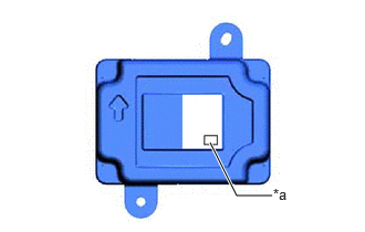
- The type of battery voltage sensor to be used varies depending on the vehicle model.
- The type of battery voltage sensor can be confirmed by the identification code of the label.
*a Identification Code AA - If the wrong type of battery voltage sensor is installed, the ignition switch cannot be turned on (READY).
- After installing the battery voltage sensor, perform the following to check that the ignition switch can be turned on (READY).
- Turn the ignition switch to on (READY).
- Turn the ignition switch off and wait for 30 seconds or more.
- Turn the ignition switch to on (READY) again.
- After the ignition switch is turned off, the radio and display receiver assembly records various types of memory and settings. As a result, after turning the ignition switch off, make sure to wait at least 2 minutes before disconnecting the cable from the negative (-) auxiliary battery terminal.
- When the cable is disconnected from the negative (-) auxiliary battery terminal and the security lock setting has been enabled, multi-display operations will be disabled upon next startup unless the password is entered. Be sure to check the security lock setting before disconnecting the cable from the negative (-) auxiliary battery terminal.
HINT:
When the cable is disconnected / reconnected to the auxiliary battery terminal, systems temporarily stop operating. However, each system has a function that completes learning the first time the system is used.
LEARNING COMPLETES WHEN VEHICLE IS DRIVEN
| Effect/Inoperative Function when Necessary Procedure not Performed | Necessary Procedure | Link |
|---|---|---|
| Lane Control System | Perform steering sensor zero point calibration | Refer to INITIALIZATION [12/2019 - ] |
| Pre-collision System | ||
| Lighting System (EXT) (w/ AFS) |
LEARNING COMPLETES WHEN VEHICLE IS OPERATED NORMALLY
| Effect/Inoperative Function when Necessary Procedure not Performed | Necessary Procedure | Link |
|---|---|---|
| Power Door Lock Control System | Initialize back door lock | Refer to INITIALIZATION [11/2023 - ] |
| Power Back Door System | Reset back door close position | Refer to INITIALIZATION [11/2023 - ] |
| Air Conditioning System | After the ignition switch is turned to ON, the servo motor standard position is recognized. | - |