Disassembly [12/2019 - 10/2022]: Procedure
- SEPARATE REAR NO. 2 DRIVE SHAFT INBOARD JOINT BOOT CLAMP
- Secure the drive shaft in a vise between aluminum plates.NOTE:
Do not overtighten the vise.
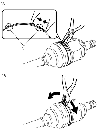
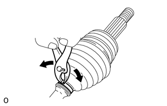
- for Type A:
*A for Type A *B for Type B *a Claw - Using needle-nose pliers, disengage the 2 claws as shown in the illustration and separate the rear No. 2 drive shaft inboard joint boot clamp.
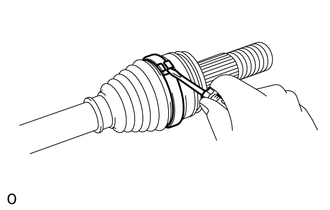
- for Type B:
- Using pliers, separate the rear No. 2 drive shaft inboard joint boot clamp as shown in the illustration.
- Secure the drive shaft in a vise between aluminum plates.
- SEPARATE REAR DRIVE SHAFT INBOARD JOINT BOOT CLAMP
HINT:
Perform the same procedure as for the rear No. 2 drive shaft inboard joint boot clamp.
- SEPARATE REAR DRIVE SHAFT INBOARD JOINT BOOT
- Separate the rear drive shaft inboard joint boot from the rear drive shaft inboard joint assembly.
- REMOVE REAR DRIVE SHAFT INBOARD JOINT ASSEMBLY
- Remove the old grease from the rear drive shaft inboard joint assembly.
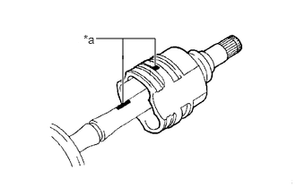
- Put matchmarks on the rear drive shaft inboard joint assembly and rear drive shaft outboard joint shaft assembly.NOTE:
Do not use a punch for the marks.
*a Matchmark - Remove the rear drive shaft inboard joint assembly from the rear drive shaft outboard joint shaft assembly.
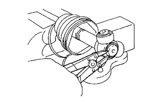
- Secure the drive shaft in a vise between aluminum plates.NOTE:
Do not overtighten the vise.
- Using a snap ring expander, remove the shaft snap ring from the rear drive shaft outboard joint shaft assembly.
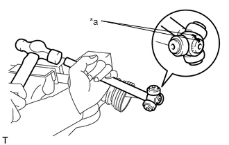
- Put matchmarks on the rear drive shaft outboard joint shaft assembly and tripod joint.NOTE:
Do not use a punch for the marks.
*a Matchmark - Using a brass bar and a hammer, tap out the tripod joint from the rear drive shaft outboard joint shaft assembly.NOTE:
- Do not tap the rollers.
- Do not drop the tripod joint.
- REMOVE REAR DRIVE SHAFT INBOARD JOINT BOOT
- Remove the rear No. 2 drive shaft inboard joint boot clamp, rear drive shaft inboard joint boot and rear drive shaft inboard joint boot clamp.
- SEPARATE REAR NO. 2 DRIVE SHAFT OUTBOARD JOINT BOOT CLAMP
- Secure the drive shaft in a vise between aluminum plates.NOTE:
Do not overtighten the vise.
- for Type A:
- for Type B:
HINT:
Perform the same procedure as for the rear No. 2 drive shaft inboard joint boot clamp.
- Secure the drive shaft in a vise between aluminum plates.
- SEPARATE REAR DRIVE SHAFT OUTBOARD JOINT BOOT CLAMP
- REMOVE REAR DRIVE SHAFT OUTBOARD JOINT BOOT
- Remove the rear drive shaft outboard joint boot clamp, rear drive shaft outboard joint boot and rear No. 2 drive shaft outboard joint boot clamp from the rear drive shaft outboard joint shaft assembly.
- Remove the old grease from the outboard joint.