Disassembly [12/2019 - ]: Procedure
- REMOVE REAR PROPELLER SHAFT ASSEMBLY NOTE:
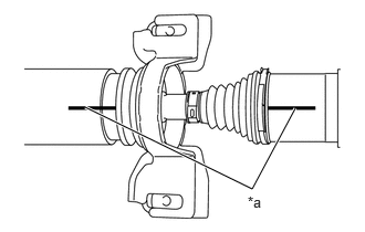
As the rear propeller shaft assembly requires alignment of multiple matchmarks, it is necessary to make separately distinguishable matchmarks.
*a Matchmark Put matchmarks on the propeller intermediate shaft assembly and rear propeller shaft assembly.
NOTE:Do not use a punch for the marks.
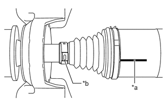
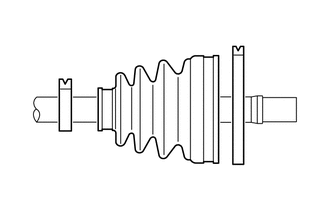
- Put a matchmark on the rear propeller shaft assembly in alignment with the crimp position of the small diameter propeller shaft boot clamp.
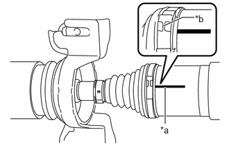
*a Matchmark *b Crimp position - Put a matchmark on the rear propeller shaft assembly in alignment with the crimp position of the large diameter propeller shaft boot clamp.
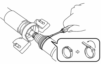
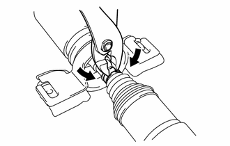
*a Matchmark *b Crimp position - Using a screwdriver, release the crimp of the large diameter propeller shaft boot clamp and separate the large diameter propeller shaft boot clamp from the propeller shaft boot.
- Using pliers, grip the crimp area of the clamp and pry the area of the small diameter propeller shaft boot clamp shown in the illustration to separate the small diameter propeller shaft boot clamp from the propeller shaft boot.
- Separate the propeller shaft boot from the rear propeller shaft assembly.
- Remove the old grease from the joint part.
- Remove the rear propeller shaft assembly from the propeller intermediate shaft assembly.
- REMOVE UNIVERSAL BOOT KIT
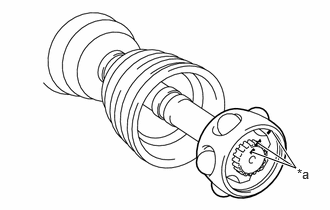
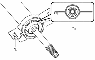
- Put matchmarks on the propeller intermediate shaft assembly, inner race and ball cage.NOTE:
Do not use a punch for the marks.
*a Matchmark - Remove the 6 balls.NOTE:
Do not drop the balls.
- Slide the ball cage toward the front side.
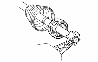
- Using a snap ring expander, remove the propeller shaft snap ring from the propeller intermediate shaft assembly.
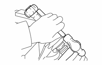
- Using a brass bar and a hammer, tap out the inner race from the propeller intermediate shaft assembly.NOTE:
Do not drop the inner race.
- Remove the ball cage.
- Remove the large diameter propeller shaft boot clamp, propeller shaft boot and small diameter propeller shaft boot clamp.
- Put matchmarks on the propeller intermediate shaft assembly, inner race and ball cage.
- REMOVE CENTER SUPPORT BEARING
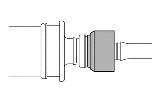
- Cut off the rubber portion of the center support bearing and remove the bracket.
*a Cleavage site *b Bracket - Remove any excess rubber so the center support bearing appears as shown in the illustration.
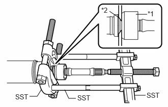
- Install SST as shown in the illustration.
*1 Center Support Bearing *2 No. 1 Dust Deflector - SST: 09950-00020
- SST: 09950-00040
- SST: 09950-40011
- 09951-04020
- 09952-04010
- 09953-04020
- 09954-04020
- 09957-04010
NOTE:Securely install SST between the center support bearing and No. 1 dust deflector.
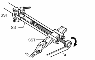
- Apply grease to the threaded area of the SST center bolt.
- Using SST, remove the center support bearing and flange from the propeller intermediate shaft assembly.
- SST: 09950-00020
- SST: 09950-00040
- SST: 09950-40011
- 09951-04020
- 09952-04010
- 09953-04020
- 09954-04020
- 09957-04010
HINT:
Perform this procedure with 2 or more people and prevent the propeller shaft from rotating.
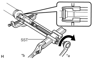
*a Turn *b Hold - Using SST, remove the No. 1 dust deflector.
*a Turn *b Hold - SST: 09950-40011
- 09951-04020
- 09952-04010
- 09953-04020
- 09954-04030
- 09955-04031
- 09957-04010
- 09958-04011
- SST: 09950-40011
- Cut off the rubber portion of the center support bearing and remove the bracket.