Reassembly [12/2019 - 11/2024]: Procedure
- INSTALL CENTER SUPPORT BEARING
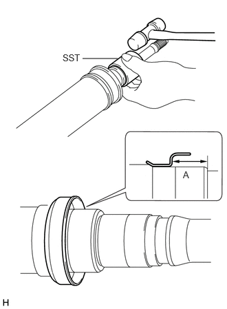
- Using SST and a plastic hammer, install a new No. 1 dust deflector to the dimension (A).
- SST: 09710-18050
- 09711-01090
Dimension (A)
17.2 to 17.6 mm (0.678 to 0.692 in.)
NOTE:Do not excessively press the No. 1 dust deflector.
- SST: 09710-18050
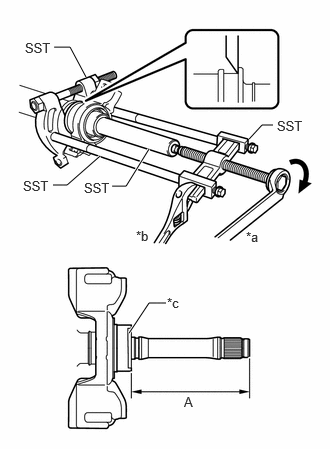
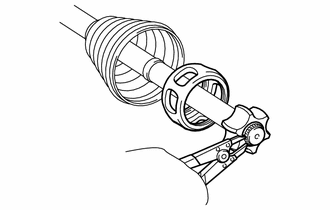
- Using SST, install a new center support bearing and flange to the propeller intermediate shaft assembly to the dimension (A).
- SST: 09612-22011
- SST: 09950-00020
- SST: 09950-00040
- SST: 09950-40011
- 09951-04020
- 09952-04010
- 09953-04020
- 09954-04040
- 09957-04010
Dimension (A)
113.5 mm (4.47 in.)
HINT:
Perform this procedure with 2 or more people and prevent the propeller shaft from rotating.
*a Turn *b Hold *c Flange
- Using SST and a plastic hammer, install a new No. 1 dust deflector to the dimension (A).
- INSTALL UNIVERSAL BOOT KIT
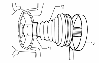
- Install each new parts to the propeller intermediate shaft assembly in the order shown in the illustration.
*1 Small Diameter Propeller Shaft Boot Clamp *2 Propeller Shaft Boot *3 Large Diameter Propeller Shaft Boot Clamp - Install the small diameter side of the propeller shaft boot to the propeller intermediate shaft assembly.
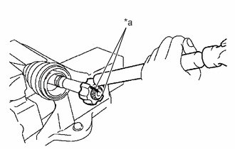
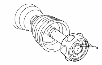
- Align the matchmarks placed before removal.
*a Matchmark - Using a brass bar and a hammer, install the inner race to the propeller intermediate shaft assembly.NOTE:
Be careful not to damage the inner race.
- Using a snap ring expander, install a new propeller shaft snap ring to the propeller intermediate shaft assembly.
- Align the matchmarks and install the ball cage to the inner race.
*a Matchmark - Install the 6 balls with grease to the inner race.NOTE:
Be careful not to drop the balls.
HINT:
Apply grease to the balls to keep them from falling.
- Install each new parts to the propeller intermediate shaft assembly in the order shown in the illustration.
- INSTALL REAR PROPELLER SHAFT ASSEMBLY
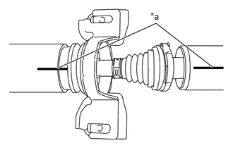
- Align the matchmarks and insert the propeller intermediate shaft assembly into the rear propeller shaft assembly.
*a Matchmark - Align the crimp position of the small diameter propeller shaft boot clamp with the matchmark of the rear propeller shaft assembly.
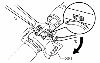
*a Matchmark *b Crimp position - Place SST onto the small diameter propeller shaft boot clamp, and while pushing it against the propeller shaft boot, slightly tighten the bolt of SST.
- SST: 09521-24010
*a Hold *b Turn - While holding SST, tighten the bolt of SST until the specified clearance value of the small diameter propeller shaft boot clamp is met.
Clearance
Below 0.8 mm (0.0315 in.)
- Remove SST.
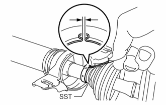
- Using SST, measure the clearance shown in the illustration.
- SST: 09240-00021
Clearance
Below 0.8 mm (0.0315 in.)
NOTE:If the clearance is not as specified, retighten SST.
- Fill the rear propeller shaft assembly and propeller shaft boot with grease.
Standard Grease Capacity
90 to 100 g (3.18 to 3.52 oz)
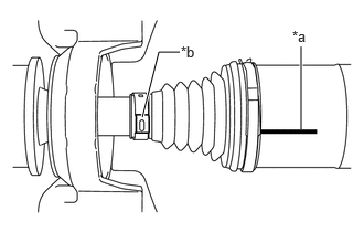
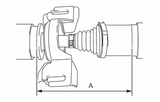
- Install the propeller shaft boot to the rear propeller shaft assembly to the specified value (A).
- Measure the distance (A) of the propeller shaft assembly shown in the illustration. If the value is not as specified, reinstall the propeller shaft boot.
Dimension (A)
189.3 to 191.7 mm (7.45 to 7.55 in.)
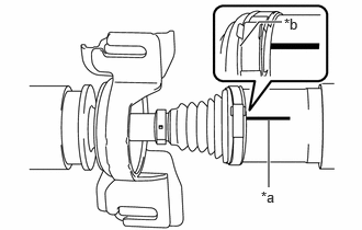
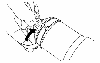
- Align the crimp position of the large diameter propeller shaft boot clamp with the matchmark of the rear propeller shaft assembly.
*a Matchmark *b Crimp position - Temporarily bend the lever from the fulcrum part of the large diameter propeller shaft boot clamp.
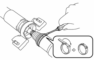
- Using a screwdriver, stake the large diameter propeller shaft boot clamp.NOTE:
Be careful not to damage the propeller shaft boot.
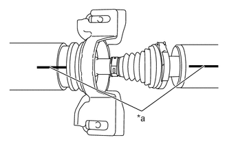
- Confirm that the matchmarks of the propeller intermediate shaft assembly and rear propeller shaft assembly are aligned.
*a Matchmark - Check whether the propeller intermediate shaft assembly dimension (A) is within specification.
Dimension (A)
189.3 to 191.7 mm (7.45 to 7.55 in.)
- Align the matchmarks and insert the propeller intermediate shaft assembly into the rear propeller shaft assembly.