Terminals Of ECM [12/2019 - 10/2021]
HINT:
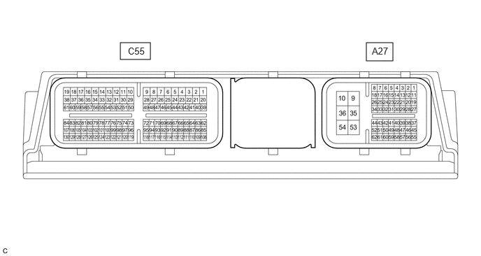
The standard voltage, resistance and waveform between each pair of the ECM terminals is shown in the table below. The appropriate conditions for checking each pair of the terminals is also indicated. The result of checks should be compared with the standard voltage, resistance and waveform for each pair of the terminals as displayed in the Specified Condition column. The illustration above can be used as a reference to identify the ECM terminal locations.
| Terminal No. (Symbol) | Terminal Description | Condition | Specified Condition |
|---|---|---|---|
| A27-1 (BATT) - A27-10 (E1) | Auxiliary battery (for measuring auxiliary battery voltage and ECM memory) | Always | 11 to 16 V |
| A27-2 (IGSW) - A27-10 (E1) | Ignition switch signal | Ignition switch ON | 11 to 14 V |
| A27-3 (VPMP) - A27-10 (E1) | Vent valve (built into canister pump module) | Ignition switch ON | 11 to 14 V |
| A27-5 (MPMP) - A27-10 (E1) | Leak detection pump (canister pump module) | Leak detection pump off | Below 3 V |
| Leak detection pump on | 11 to 14 V | ||
| A27-6 (FPC) - A27-10 (E1) | Fuel pump control | Engine stopped, ignition switch ON | Below 1.5 V |
| A27-7 (CAN+) - A27-10 (E1) | CAN communication line | Engine stopped, ignition switch ON | Pulse generation (See waveform 1) |
| A27-8 (CANH) - A27-10 (E1) | CAN communication line | Engine stopped, ignition switch ON | Pulse generation (See waveform 1) |
| A27-9 (+B) - A27-10 (E1) |
|
Ignition switch ON | 11 to 14 V |
| A27-10 (E1) - Body ground | Ground | Always | Below 1 Ω |
| A27-11 (CCB+) - A27-10 (E1) | Fuel vapor containment valve signal | Ignition switch ON | Pulse generation (See waveform 2) |
| A27-12 (CCA+) - A27-10 (E1) | Fuel vapor containment valve signal | Ignition switch ON | Pulse generation (See waveform 2) |
| A27-15 (MREL) - A27-10 (E1) | EFI-MAIN NO. 1 relay operation signal | Ignition switch ON | Below 1.5 V |
| A27-16 (NEO) - A27-10 (E1) | Crankshaft revolution signal | Idling with warm engine | Pulse generation (See waveform 3) |
| A27-17 (CAN-) - A27-10 (E1) | CAN communication line | Engine stopped, ignition switch ON | Pulse generation (See waveform 4) |
| A27-18 (CANL) - A27-10 (E1) | CAN communication line | Engine stopped, ignition switch ON | Pulse generation (See waveform 4) |
| A27-19 (CCB-) - A27-10 (E1) | Fuel vapor containment valve signal | Ignition switch ON | Pulse generation (See waveform 2) |
| A27-20 (CCA-) - A27-10 (E1) | Fuel vapor containment valve signal | Ignition switch ON | Pulse generation (See waveform 2) |
| A27-24 (G2O) - A27-10 (E1) | Camshaft revolution signal | Idling with warm engine | Pulse generation (See waveform 5) |
| A27-31 (LIDO) - A27-10 (E1) | Fuel lid courtesy switch signal | Fuel lid closed | 11 to 14 V |
| Fuel lid open | Below 1.0 V | ||
| A27-32 (RFC) - A27-10 (E1) | Cooling fan control signal | Ignition switch ON, A/C switch on (max cool) | Pulse generation (See waveform 6) |
| A27-34 (IREL) - A27-10 (E1) | D INJ relay operation signal | Ignition switch ON | 11 to 14 V |
| A27-35 (+B2) - A27-10 (E1) | Power source of ECM | Ignition switch ON | 11 to 14 V |
| A27-36 (E2) - Body ground | Ground | Always | Below 1 Ω |
| A27-38 (FUEL) - A27-10 (E1) | Fuel lid opener switch signal | Fuel lid opener switch pressed | Below 1.0 V |
| Fuel lid opener switch not pressed | 4.5 to 5.5 V | ||
| A27-45 (EC) - Body ground | Ground | Always | Below 1 Ω |
| A27-41 (LSTM) - A27-10 (E1) | Fuel lid operation signal for combination meter assembly | Multi-information display displaying "Close Fuel Lid" | Pulse generation (See waveform 7) |
| Multi-information display displaying "Ready to Refuel" | Pulse generation (See waveform 8) |
||
| Ignition switch ON | 11 to 14 V | ||
| A27-44 (FREL) - A27-10 (E1) | Fuel lid lock with motor assembly operation signal | Fuel lid lock with motor assembly operating | Below 1.0 V |
| Fuel lid lock with motor assembly not operating | 11 to 14 V | ||
| A27-48 (VCPP) - A27-49 (EPPM) | Power source for canister pressure sensor (specific voltage) | Ignition switch ON | 4.5 to 5.5 V |
| A27-50 (PPMP) - A27-49 (EPPM) | Canister pressure sensor (built into canister pump module) | Ignition switch ON | 3.0 to 3.6 V |
| A27-53 (+BD1) - A27-10 (E1) | Power source of ECU (injector driver) | Ignition switch ON | 11 to 14 V |
| A27-54 (E1D1) - Body ground | Ground | Always | Below 1 Ω |
| A27-57 (VPTK) - A27-56 (EPTK) | Power source of fuel tank pressure sensor (specific voltage) | Engine stopped, ignition switch ON | 4.75 to 5.25 V |
| A27-55 (PTNK) - A27-56 (EPTK) | Fuel tank pressure sensor signal | Engine stopped, ignition switch ON | 0.27 to 4.73 V |
| C55-1 (M-) - A27-10 (E1) | Throttle actuator operation signal (negative signal) | Idling with warm engine | Pulse generation (See waveform 9) |
| C55-2 (M+) - A27-10 (E1) | Throttle actuator operation signal (positive terminal) | Idling with warm engine | Pulse generation (See waveform 10) |
| C55-3 (EGA+) - A27-10 (E1) | EGR valve assembly operation signal | Idling with warm engine | Pulse generation (See waveform 11) |
| C55-4 (EGA-) - A27-10 (E1) | EGR valve assembly operation signal | Idling with warm engine | Pulse generation (See waveform 11) |
| C55-5 (EGB-) - A27-10 (E1) | EGR valve assembly operation signal | Idling with warm engine | Pulse generation (See waveform 11) |
| C55-6 (EGB+) - A27-10 (E1) | EGR valve assembly operation signal | Idling with warm engine | Pulse generation (See waveform 11) |
| C55-7 (HTHM) - A27-10 (E1) | Thermostat heater (water inlet with thermostat sub-assembly) operation signal | Ignition switch ON | 11 to 14 V |
| C55-8 (HA1B) - A27-10 (E1) | Air fuel ratio sensor (sensor 2) heater operation signal | Ignition switch ON | 11 to 14 V |
| Idling with cold engine | Pulse generation (See waveform 12) |
||
| C55-9 (HA1A) - A27-10 (E1) | Air fuel ratio sensor (sensor 1) heater operation signal | Ignition switch ON | 11 to 14 V |
| Idling with cold engine | Pulse generation (See waveform 13) |
||
| C55-10 (#2D-) - A27-10 (E1) | Direct fuel injector assembly signal (No. 2 cylinder) | Idling with warm engine, Data List item "Injection Mode" displaying "Direct" | Pulse generation (See waveform 14) |
| C55-11 (#2D+) - A27-10 (E1) | Direct fuel injector assembly signal (No. 2 cylinder) | Idling with warm engine, Data List item "Injection Mode" displaying "Direct" | Pulse generation (See waveform 14) |
| C55-12 (#3D+) - A27-10 (E1) | Direct fuel injector assembly signal (No. 3 cylinder) | Idling with warm engine, Data List item "Injection Mode" displaying "Direct" | Pulse generation (See waveform 14) |
| C55-13 (#3D-) - A27-10 (E1) | Direct fuel injector assembly signal (No. 3 cylinder) | Idling with warm engine, Data List item "Injection Mode" displaying "Direct" | Pulse generation (See waveform 14) |
| C55-14 (#4D-) - A27-10 (E1) | Direct fuel injector assembly signal (No. 4 cylinder) | Idling with warm engine, Data List item "Injection Mode" displaying "Direct" | Pulse generation (See waveform 14) |
| C55-15 (#4D+) - A27-10 (E1) | Direct fuel injector assembly signal (No. 4 cylinder) | Idling with warm engine, Data List item "Injection Mode" displaying "Direct" | Pulse generation (See waveform 14) |
| C55-16 (#1D+) - A27-10 (E1) | Direct fuel injector assembly signal (No. 1 cylinder) | Idling with warm engine, Data List item "Injection Mode" displaying "Direct" | Pulse generation (See waveform 14) |
| C55-17 (#1D-) - A27-10 (E1) | Direct fuel injector assembly signal (No. 1 cylinder) | Idling with warm engine, Data List item "Injection Mode" displaying "Direct" | Pulse generation (See waveform 14) |
| C55-18 (FP1-) - A27-10 (E1) | Fuel pump assembly (for high pressure side) signal | Idling with warm engine, Data List item "Injection Mode" displaying "Direct" | Pulse generation (See waveform 15) |
| C55-19 (FP1+) - A27-10 (E1) | Fuel pump assembly (for high pressure side) signal | Idling with warm engine, Data List item "Injection Mode" displaying "Direct" | Pulse generation (See waveform 15) |
| C55-20 (VOP-) - A27-10 (E1) | Oil pressure control valve operation signal | Idling with warm engine | Pulse generation (See waveform 16) |
| C55-21 (VOP+) - A27-10 (E1) | Oil pressure control valve operation signal | Idling with warm engine | Pulse generation (See waveform 16) |
| C55-26 (OE1+) - C55-25 (OE1-) | Cam timing oil control solenoid assembly operation signal | Idling | Pulse generation (See waveform 17) |
| C55-28 (EDT1) - A27-10 (E1) | Cam timing control motor with EDU assembly signal | Idling with warm engine | Pulse generation (See waveform 18) |
| C55-42 (WSV1) - A27-10 (E1) | Flow shutting valve operation signal | Ignition switch ON | 11 to 14 V |
| C55-46 (IGT4) - A27-10 (E1) | No. 4 ignition coil assembly signal (ignition signal) |
Idling with warm engine | Pulse generation (See waveform 19) |
| C55-47 (IGT3) - A27-10 (E1) | No. 3 ignition coil assembly signal (ignition signal) |
Idling with warm engine | Pulse generation (See waveform 19) |
| C55-48 (IGT2) - A27-10 (E1) | No. 2 ignition coil assembly signal (ignition signal) |
Idling with warm engine | Pulse generation (See waveform 19) |
| C55-49 (IGT1) - A27-10 (E1) | No. 1 ignition coil assembly signal (ignition signal) |
Idling with warm engine | Pulse generation (See waveform 19) |
| C55-50 (WPO) - A27-10 (E1) | Water inlet housing with water pump sub-assembly signal | Idling with warm engine | Pulse generation (See waveform 20) |
| C55-51 (WPI) - A27-10 (E1) | Water inlet housing with water pump sub-assembly signal | Idling with warm engine | Pulse generation (See waveform 21) |
| C55-66 (PRG) - A27-10 (E1) | Purge VSV operation signal | Ignition switch ON | 11 to 14 V |
| Idling with warm engine, under purge control | Pulse generation (See waveform 22) |
||
| C55-70 (EMR1) - A27-10 (E1) | Cam timing control motor with EDU assembly signal | Idling with warm engine | Pulse generation (See waveform 23) |
| C55-71 (EMF1) - A27-10 (E1) | Cam timing control motor with EDU assembly signal | Idling with warm engine | Below 5.0 V |
| C55-72 (EMD1) - A27-10 (E1) | Cam timing control motor with EDU assembly signal | Idling with warm engine | Pulse generation (See waveform 24) |
| C55-73 (#40) - A27-10 (E1) | Port fuel injector assembly signal (No. 4 cylinder) | Idling with warm engine (Data List item "Injection Mode" displaying "Port") | Pulse generation (See waveform 25) |
| C55-74 (#30) - A27-10 (E1) | Port fuel injector assembly signal (No. 3 cylinder) | Idling with warm engine (Data List item "Injection Mode" displaying "Port") | Pulse generation (See waveform 25) |
| C55-75 (#20) - A27-10 (E1) | Port fuel injector assembly signal (No. 2 cylinder) | Idling with warm engine (Data List item "Injection Mode" displaying "Port") | Pulse generation (See waveform 25) |
| C55-76 (#10) - A27-10 (E1) | Port fuel injector assembly signal (No. 1 cylinder) | Idling with warm engine (Data List item "Injection Mode" displaying "Port") | Pulse generation (See waveform 25) |
| C55-78 (VCVG) - A27-10 (E1) | Power source of mass air flow meter sub-assembly (specific voltage) | Ignition switch ON | 4.8 to 5.2 V |
| C55-84 (VCPF) - A27-10 (E1) | Power source of No. 2 fuel pressure sensor (for low pressure side) (specific voltage) | Ignition switch ON | 4.75 to 5.25 V |
| C55-87 (VTA2) - C55-110 (ETA) | Throttle position sensor signal (for sensor malfunction detection) | Engine stopped, ignition switch ON, accelerator pedal fully released | 2.1 to 3.1 V |
| C55-88 (VCV1) - A27-10 (E1) | Power source of camshaft position sensor (for intake camshaft) (specific voltage) | Ignition switch ON | 4.5 to 5.5 V |
| C55-90 (VV1+) - C55-89 (VV1-) | Camshaft position sensor (for intake camshaft) signal | Idling with warm engine | Pulse generation (See waveform 26) |
| C55-91 (EV1+) - C55-114 (EV1-) | Camshaft position sensor (for exhaust camshaft) signal | Idling with warm engine | Pulse generation (See waveform 26) |
| C55-93 (NE+) - C55-115 (NE-) | Crankshaft position sensor signal | Idling with warm engine | Pulse generation (See waveform 27) |
| C55-94 (A1A-) - A27-10 (E1) | Air fuel ratio sensor (sensor 1) signal | Ignition switch ON | 1.24 to 4.22 V |
| C55-95 (A1A+) - A27-10 (E1) | Air fuel ratio sensor (sensor 1) signal | Ignition switch ON | 1.46 to 4.22 V |
| C55-97 (PR) - C55-96 (EPR) | Fuel pressure sensor (for high pressure side) signal | Idling with warm engine | 0.5 to 4.5 V |
| C55-98 (VCPR) - C55-96 (EPR) | Power source of fuel pressure sensor (for high pressure side) (specific voltage) | Ignition switch ON | 4.75 to 5.25 V |
| C55-99 (VCPE) - C55-100 (EPEO) | Power source of oil pressure and temperature sensor (specific voltage) | Ignition switch ON | 4.5 to 5.5 V |
| C55-101 (VG) - C55-79 (E2G) | Mass air flow meter sub-assembly signal | Ignition switch ON | Pulse generation (See waveform 28) |
| C55-102 (THA) - C55-79 (E2G) | Intake air temperature sensor (mass air flow meter sub-assembly) signal | Idling, intake air temperature 0 to 80°C (32 to 176°F) | 0.5 to 3.4 V |
| C55-107 (PFL) - C55-61 (EPFL) | No. 2 fuel pressure sensor (for low pressure side) signal | Idling with warm engine | 0.57 to 4.88 V |
| C55-108 (VTA1) - C55-110 (ETA) | Throttle position sensor signal (for engine control) | Engine stopped, ignition switch ON, accelerator pedal fully released | 0.6 to 1.1 V |
| C55-109 (VCTA) - C55-110 (ETA) | Power source of throttle position sensor (specific voltage) | Engine stopped, ignition switch ON | 4.5 to 5.5 V |
| C55-111 (KNK1) - C55-112 (EKNK) | Knock control sensor signal | Engine speed maintained at 2500 rpm after warming up engine | Pulse generation (See waveform 29) |
| C55-113 (VCE1) - A27-10 (E1) | Power source of camshaft position sensor (for exhaust camshaft) (specific voltage) | Ignition switch ON | 4.5 to 5.5 V |
| C55-116 (VCNE) - A27-10 (E1) | Power source of crankshaft position sensor (specific voltage) | Ignition switch ON | 4.5 to 5.5 V |
| C55-117 (A1B-) - A27-10 (E1) | Air fuel ratio sensor (sensor 2) signal | Ignition switch ON | 1.17 to 4.49 V |
| C55-118 (A1B+) - A27-10 (E1) | Air fuel ratio sensor (sensor 2) signal | Ignition switch ON | 1.53 to 5.96 V |
| C55-120 (PIM) - C55-119 (EPIM) | Manifold absolute pressure sensor signal | Ignition switch ON | 3.0 to 4.5 V |
| C55-121 (VCPM) - C55-119 (EPIM) | Power source of manifold absolute pressure sensor (specific voltage) | Ignition switch ON | 4.75 to 5.25 V |
| C55-122 (PEO) - C55-100 (EPEO) | Engine oil pressure sensor signal | Idling with warm engine | 0.5 to 4.5 V |
| C55-123 (THEO) - C55-100 (EPEO) | Engine oil temperature sensor signal | Ignition switch ON | 0.14 to 4.93 V |
| C55-125 (THW) - C55-124 (ETHW) | Engine coolant temperature sensor signal | Idling, engine coolant temperature 75 to 100°C (167 to 212°F) | 0.2 to 1.0 V |
| C55-129 (THTW) - C55-130 (ETHT) | No. 2 engine coolant temperature sensor signal | Idling, engine coolant temperature 75 to 100°C (167 to 212°F) | 0.2 to 1.0 V |
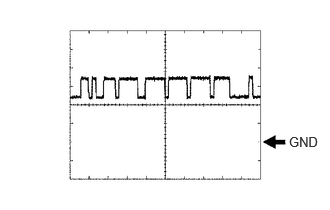
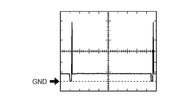
- WAVEFORM 1 CAN COMMUNICATION SIGNAL (REFERENCE)
ECM Terminal Name Between CANH and E1
Between CAN+ and E1Tester Range 1 V/DIV., 10 μs./DIV. Condition Engine stopped, ignition switch ON HINT:
The waveform varies depending on the CAN communication signal.
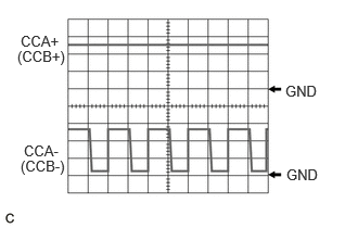
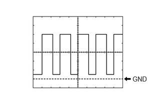
- WAVEFORM 2 FUEL VAPOR-CONTAINMENT VALVE OPERATION SIGNAL
ECM Terminal Name CH1: Between CCA+ and E1
CH2: Between CCA- and E1CH1: Between CCB+ and E1
CH2: Between CCB- and E1Tester Range 5 V/DIV., 5 μs./DIV. Condition Ignition switch ON HINT:
When the fuel vapor-containment valve is operating, a waveform is produced at each terminal.
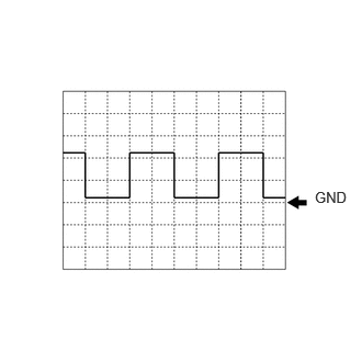
- WAVEFORM 3 CRANKSHAFT REVOLUTION SIGNAL FROM ECM TO INVERTER WITH CONVERTER ASSEMBLY
ECM Terminal Name Between NEO and E1 Tester Range 5 V/DIV., 20 ms./DIV. Condition Idling with warm engine HINT:
The wavelength becomes shorter as the engine speed increases.
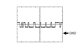
- WAVEFORM 4 CAN COMMUNICATION SIGNAL (REFERENCE)
ECM Terminal Name Between CANL and E1
Between CAN- and E1Tester Range 1 V/DIV., 10 μs./DIV. Condition Engine stopped, ignition switch ON HINT:
The waveform varies depending on the CAN communication signal.
- WAVEFORM 5 CAMSHAFT REVOLUTION SIGNAL FROM ECM TO INVERTER WITH CONVERTER ASSEMBLY
ECM Terminal Name Between G2O and E1 Tester Range 5 V/DIV., 20 ms./DIV. Condition Idling with warm engine HINT:
The wavelength becomes shorter as the engine speed increases.
- WAVEFORM 6 COOLING FAN CONTROL SIGNAL
ECM Terminal Name Between RFC and E1 Tester Range 1 V/DIV., 2 ms./DIV. Condition Ignition switch ON, A/C switch on (max cool) HINT:
The duty ratio varies depending on the engine coolant temperature.
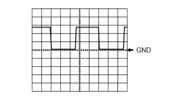
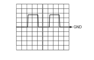
- WAVEFORM 7 FUEL LID OPERATION SIGNAL FOR COMBINATION METER ASSEMBLY
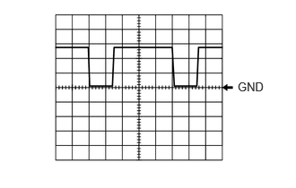
ECM Terminal Name Between LSTM and E1 Tester Range 5 V/DIV., 20 ms./DIV. Condition Multi-information display displaying "Close Fuel Lid" - WAVEFORM 8 FUEL LID OPERATION SIGNAL FOR COMBINATION METER ASSEMBLY
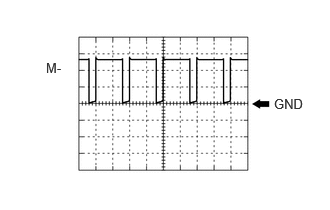
ECM Terminal Name Between LSTM and E1 Tester Range 5 V/DIV., 20 ms./DIV. Condition Multi-information display displaying "Ready to Refuel" - WAVEFORM 9 THROTTLE ACTUATOR OPERATION SIGNAL (NEGATIVE TERMINAL)
ECM Terminal Name Between M- and E1 Tester Range 5 V/DIV., 1 ms./DIV. Condition Idling with warm engine HINT:
The duty ratio varies depending on the throttle actuator operation.
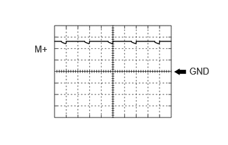
- WAVEFORM 10 THROTTLE ACTUATOR OPERATION SIGNAL (POSITIVE TERMINAL)
ECM Terminal Name Between M+ and E1 Tester Range 5 V/DIV., 1 ms./DIV. Condition Idling with warm engine HINT:
The duty ratio varies depending on the throttle actuator operation.
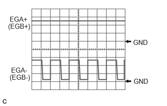
- WAVEFORM 11 EGR VALVE ASSEMBLY OPERATION SIGNAL
ECM Terminal Name CH1: Between EGA+ and E1
CH2: Between EGA- and E1CH1: Between EGB+ and E1
CH2: Between EGB- and E1Tester Range 5 V/DIV., 5 μs./DIV. Condition Idling with warm engine HINT:
When the EGR valve assembly is operating, a waveform is produced at each terminal.
- WAVEFORM 12 AIR FUEL RATIO SENSOR (SENSOR 2) HEATER OPERATION SIGNAL
ECM Terminal Name Between HA1B and E1 Tester Range 5 V/DIV., 10 ms./DIV. Condition Idling with cold engine - WAVEFORM 13 AIR FUEL RATIO SENSOR (SENSOR 1) HEATER OPERATION SIGNAL
ECM Terminal Name Between HA1A and E1 Tester Range 5 V/DIV., 10 ms./DIV. Condition Idling with cold engine - WAVEFORM 14 NO. 1 (TO NO. 4) DIRECT FUEL INJECTOR ASSEMBLY SIGNAL
ECM Terminal Name CH1: Between #1D+ and E1
CH2: Between #1D- and E1CH1: Between #2D+ and E1
CH2: Between #2D- and E1CH1: Between #3D+ and E1
CH2: Between #3D- and E1CH1: Between #4D+ and E1
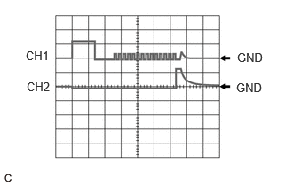
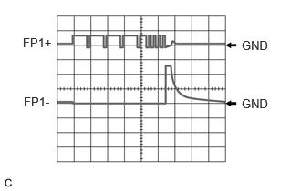
CH2: Between #4D- and E1Tester Range 50 V/DIV., 200 μs./DIV. Condition Idling with warm engine, Data List item "Injection Mode" displaying "Direct" - WAVEFORM 15 FUEL PUMP ASSEMBLY (FOR HIGH PRESSURE SIDE) SIGNAL
ECM Terminal Name CH1: Between FP1+ and E1
CH2: Between FP1- and E1Tester Range 20 V/DIV., 500 μs./DIV. Condition Idling with warm engine, Data List item "Injection Mode" displaying "Direct" - WAVEFORM 16 OIL PRESSURE CONTROL VALVE OPERATION SIGNAL
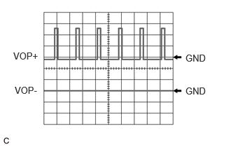
ECM Terminal Name CH1: Between VOP+ and E1
CH2: Between VOP- and E1Tester Range 5 V/DIV., 20 ms./DIV. Condition Idling with warm engine - WAVEFORM 17 CAM TIMING OIL CONTROL SOLENOID ASSEMBLY OPERATION SIGNAL
ECM Terminal Name Between OE1+ and OE1- Tester Range 5 V/DIV., 1 ms./DIV. Condition Idling - WAVEFORM 18 CAM TIMING CONTROL MOTOR WITH EDU ASSEMBLY SIGNAL (EDT SIGNAL)
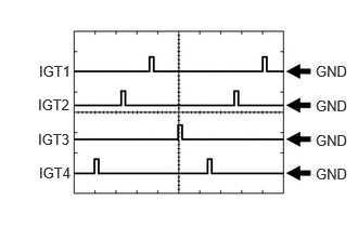
ECM Terminal Name Between EDT1 and E1 Tester Range 1 V/DIV., 5 ms./DIV. Condition Idling with warm engine - WAVEFORM 19 IGNITION COIL ASSEMBLY SIGNAL (IGT SIGNAL)
ECM Terminal Name Between IGT (1 to 4) and E1 Tester Range 5 V/DIV., 20 ms./DIV. Condition Idling with warm engine HINT:
The wavelength becomes shorter as the engine speed increases.
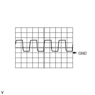
- WAVEFORM 20 WATER INLET HOUSING WITH WATER PUMP SUB-ASSEMBLY SIGNAL (FROM ECM TO WATER INLET HOUSING WITH WATER PUMP SUB-ASSEMBLY)
ECM Terminal Name Between WPO and E1 Tester Range 5 V/DIV., 20 ms./DIV. Condition Idling with warm engine HINT:
The duty ratio varies depending on the water inlet housing with water pump sub-assembly speed.
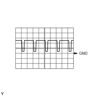
- WAVEFORM 21 WATER INLET HOUSING WITH WATER PUMP SUB-ASSEMBLY SIGNAL (FROM WATER INLET HOUSING WITH WATER PUMP SUB-ASSEMBLY TO ECM)
ECM Terminal Name Between WPI and E1 Tester Range 5 V/DIV., 20 ms./DIV. Condition Idling with warm engine HINT:
The wavelength becomes shorter as the water inlet housing with water pump sub-assembly speed increases.
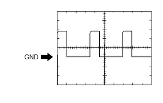
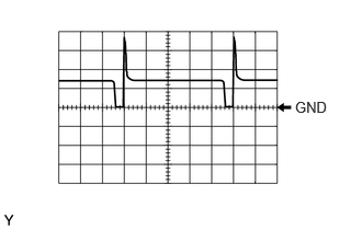
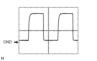
- WAVEFORM 22 PURGE VSV OPERATION SIGNAL
ECM Terminal Name Between PRG and E1 Tester Range 10 V/DIV., 20 ms./DIV. Condition Idling with warm engine, under purge control HINT:
If the waveform is not similar to the illustration, check the waveform again after idling for 10 minutes or more.
- WAVEFORM 23 CAM TIMING CONTROL MOTOR WITH EDU ASSEMBLY SIGNAL (EMR SIGNAL)
ECM Terminal Name Between EMR1 and E1 Tester Range 2 V/DIV., 5 ms./DIV. Condition Idling with warm engine HINT:
The wavelength becomes shorter as the engine speed increases.
- WAVEFORM 24 CAM TIMING CONTROL MOTOR WITH EDU ASSEMBLY SIGNAL (EMD SIGNAL)
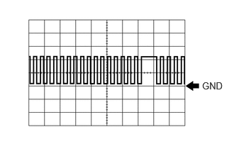
ECM Terminal Name Between EMD1 and E1 Tester Range 2 V/DIV., 100 ms./DIV. Condition Idling with warm engine - WAVEFORM 25 NO. 1 (TO NO. 4) PORT FUEL INJECTOR ASSEMBLY SIGNAL
ECM Terminal Name Between #10 (to #40) and E1 Tester Range 20 V/DIV., 20 ms./DIV. Condition Idling with warm engine (Data List item "Injection Mode" displaying "Port") HINT:
- The wavelength becomes shorter as the engine speed increases.
- When the port injection injectors are operating, Port is displayed for Injection Mode of the Data List.
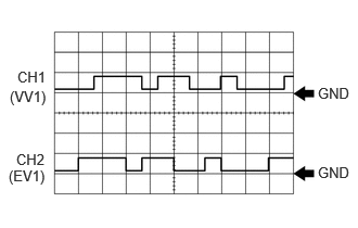
- WAVEFORM 26 CAMSHAFT POSITION SENSOR SIGNAL
ECM Terminal Name CH1: Between VV1+ and VV1-
CH2: Between EV1+ and EV1-Tester Range 5 V/DIV., 20 ms./DIV. Condition Idling with warm engine HINT:
The wavelength becomes shorter as the engine speed increases.
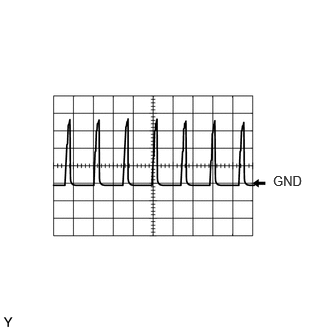
- WAVEFORM 27 CRANKSHAFT POSITION SENSOR SIGNAL
ECM Terminal Name Between NE+ and NE- Tester Range 2 V/DIV., 20 ms./DIV. Condition Idling with warm engine HINT:
The wavelength becomes shorter as the engine speed increases.
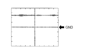
- WAVEFORM 28 MASS AIR FLOW METER SUB-ASSEMBLY SIGNAL
ECM Terminal Name Between VG and E2G Tester Range 1 V/DIV., 100 μs./DIV. Condition Ignition switch ON - WAVEFORM 29 KNOCK CONTROL SENSOR SIGNAL
ECM Terminal Name Between KNK1 and EKNK Tester Range 1 V/DIV., 1 ms./DIV. Condition Engine speed maintained at 2500 rpm after warming up engine HINT:
- The wavelength becomes shorter as the engine speed increases.
- The waveforms and amplitudes displayed differ slightly depending on the vehicle.