Reverse Signal Circuit [12/2019 - 10/2022]: Procedure
- CHECK VEHICLE TYPE
Result
Result Proceed to For Gasoline Model A For HV Model B Result:
B
See step 5
Result:
A
See step 2
- CHECK VEHICLE SIGNAL (DISPLAY CHECK MODE)
- Enter the "Function Check/Setting I" mode and select "Vehicle Signal".
w/ Navigation System:
Refer to OPERATION CHECK [12/2019 - 10/2022]
w/ Audio and Visual System:
Refer to OPERATION CHECK [12/2019 - 10/2022]
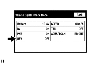
- Check that the "REV" item on the display changes between ON and OFF according to the shift lever position.
OK
Shift Lever Position Display R ON Except R OFF HINT:
This display is updated once per second. As a result, it is normal for the display to lag behind the actual shift lever position.
Result
Proceed to OK NG
Result:
OK
PROCEED TO NEXT SUSPECTED AREA SHOWN IN PROBLEM SYMPTOMS TABLE. Refer to PROBLEM SYMPTOMS TABLE [12/2019 - 10/2022]
Result:
NG
See step 3
- Enter the "Function Check/Setting I" mode and select "Vehicle Signal".
- INSPECT PARK/NEUTRAL POSITION SWITCH ASSEMBLY
- Remove the park/neutral position switch assembly.
For UA80E:
Refer to REMOVAL [12/2019 - 10/2022]
For UA80F:
Refer to REMOVAL [12/2019 - 10/2022]
- Inspect the park/neutral position switch assembly.
For UA80E:
Refer to INSPECTION [12/2019 - 10/2022]
For UA80F:
Refer to INSPECTION [12/2019 - 10/2022]
Result
Proceed to OK NG
Result:
NG
REPLACE PARK/NEUTRAL POSITION SWITCH ASSEMBLY
For UA80E:
Refer to REMOVAL [12/2019 - 10/2022]
For UA80F:
Refer to REMOVAL [12/2019 - 10/2022]
Result:
OK
See step 4
- Remove the park/neutral position switch assembly.
- CHECK HARNESS AND CONNECTOR (PARK/NEUTRAL POSITION SWITCH ASSEMBLY - RADIO AND DISPLAY RECEIVER ASSEMBLY AND BATTERY)
- Disconnect the C52 park/neutral position switch assembly connector.
- Disconnect the H1 radio and display receiver assembly connector.
- Measure the voltage according to the value(s) in the table below.
Standard Voltage
Tester Connection Switch Condition Specified Condition C52-1 (RB) - Body ground Ignition switch ON 11 to 14 V - Measure the resistance according to the value(s) in the table below.
Standard Resistance
Tester Connection Condition Specified Condition C52-2 (RL) - H1-28 (REV) Always Below 1 Ω C52-2 (RL) - Body ground Always 10 kΩ or higher Result
Proceed to OK NG
Result:
OK
PROCEED TO NEXT SUSPECTED AREA SHOWN IN PROBLEM SYMPTOMS TABLE. Refer to PROBLEM SYMPTOMS TABLE [12/2019 - 10/2022]
Result:
NG
REPAIR OR REPLACE HARNESS OR CONNECTOR
- CHECK VEHICLE SIGNAL (DISPLAY CHECK MODE)
- Enter the "Function Check/Setting I" mode and select "Vehicle Signal".
w/ Navigation System:
Refer to OPERATION CHECK [12/2019 - 10/2022]
w/ Audio and Visual System:
Refer to OPERATION CHECK [12/2019 - 10/2022]
- Check that the "REV" item on the display changes between ON and OFF according to the shift lever position.
OK
Shift Lever Position Display R ON Except R OFF HINT:
This display is updated once per second. As a result, it is normal for the display to lag behind the actual shift lever position.
Result
Result Proceed to OK A NG (w/ Navigation System) B NG (w/ Audio and Visual System) C
Result:
A
PROCEED TO NEXT SUSPECTED AREA SHOWN IN PROBLEM SYMPTOMS TABLE. Refer to PROBLEM SYMPTOMS TABLE [12/2019 - 10/2022]
Result:
B
GO TO NAVIGATION SYSTEM. Refer to HOW TO PROCEED WITH TROUBLESHOOTING [12/2019 - 10/2022]
Result:
C
GO TO AUDIO AND VISUAL SYSTEM. Refer to HOW TO PROCEED WITH TROUBLESHOOTING [12/2019 - 10/2022]
- Enter the "Function Check/Setting I" mode and select "Vehicle Signal".