Speaker Circuit [12/2019 - 10/2022]: Procedure
- CHECK MODEL
- Choose the model to be inspected.
Result
Result Proceed to w/o Stereo Component Amplifier Assembly A w/ Stereo Component Amplifier Assembly B
Result:
B
See step 10
Result:
A
See step 2
- Choose the model to be inspected.
- CHECK SPEAKER (OPERATION CHECK)
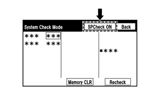
- Enter the "System Check Mode" screen. Refer to Check Speaker in Operation Check.
Refer to OPERATION CHECK [12/2019 - 10/2022]
- Perform the operation check above and determine the speaker that is not operating.
HINT:
If sound cannot be heard from any speaker, inspect all of them.
Result
Not Operating Speaker Proceed to Front No. 1 speaker assembly or front No. 2 speaker assembly
(w/o Telematics Transceiver)A Front No. 1 speaker assembly or front No. 2 speaker assembly
(w/ Telematics Transceiver)B Rear speaker assembly C
Result:
B
See step 4
Result:
C
See step 8
Result:
A
See step 3
- Enter the "System Check Mode" screen. Refer to Check Speaker in Operation Check.
- CHECK HARNESS AND CONNECTOR (RADIO AND DISPLAY RECEIVER ASSEMBLY - FRONT NO. 1 SPEAKER ASSEMBLY - FRONT NO. 2 SPEAKER ASSEMBLY)
- Disconnect the H9 radio and display receiver assembly connector.
- Disconnect the J1 and J17 front No. 1 speaker assembly connectors.
- Disconnect the H71 and H73 front No. 2 speaker assembly connectors.
- Measure the resistance according to the value (s) in the table below.
Standard Resistance
Tester Connection Condition Specified Condition H9-1 (FR+) - H71-4 (TWR+) Always Below 1 Ω H9-6 (FR-) - H71-2 (TWR-) Always Below 1 Ω H9-2 (FL+) - H73-4 (TWL+) Always Below 1 Ω H9-7 (FL-) - H73-2 (TWL-) Always Below 1 Ω J1-2 - H71-3 (+) Always Below 1 Ω J1-1 - H71-1 (-) Always Below 1 Ω J17-2 - H73-3 (+) Always Below 1 Ω J17-1 - H73-1 (-) Always Below 1 Ω H9-1 (FR+) or H71-4 (TWR+) - Body ground Always 10 kΩ or higher H9-6 (FR-) or H71-2 (TWR-) - Body ground Always 10 kΩ or higher H9-2 (FL+) or H73-4 (TWL+) - Body ground Always 10 kΩ or higher H9-7 (FL-) or H73-2 (TWL-) - Body ground Always 10 kΩ or higher J1-2 or H71-3 (+) - Body ground Always 10 kΩ or higher J1-1 or H71-1 (-) - Body ground Always 10 kΩ or higher J17-2 or H73-3 (+) - Body ground Always 10 kΩ or higher J17-1 or H73-1 (-) - Body ground Always 10 kΩ or higher Result
Proceed to OK NG
Result:
OK
See step 6
Result:
NG
REPAIR OR REPLACE HARNESS OR CONNECTOR
- CHECK HARNESS AND CONNECTOR (RADIO AND DISPLAY RECEIVER ASSEMBLY - DCM (TELEMATICS TRANSCEIVER) - FRONT NO. 1 SPEAKER ASSEMBLY - FRONT NO. 2 SPEAKER ASSEMBLY)
- Disconnect the H9 radio and display receiver assembly connector.
- Disconnect the J1 and J17 front No. 1 speaker assembly connectors.
- Disconnect the H71 and H73 front No. 2 speaker assembly connectors.
- Disconnect the H12 DCM (telematics transceiver) connector.
- Measure the resistance according to the value (s) in the table below.
Standard Resistance
Tester Connection Condition Specified Condition H9-1 (FR+) - H12-1 (SPI+) Always Below 1 Ω H9-6 (FR-) - H12-2 (SPI-) Always Below 1 Ω H12-3 (SPO+) - H71-4 (TWR+) Always Below 1 Ω H12-4 (SPO-) - H71-2 (TWR-) Always Below 1 Ω H9-2 (FL+) - H73-4 (TWL+) Always Below 1 Ω H9-7 (FL-) - H73-2 (TWL-) Always Below 1 Ω J1-2 - H71-3 (+) Always Below 1 Ω J1-1 - H71-1 (-) Always Below 1 Ω J17-2 - H73-3 (+) Always Below 1 Ω J17-1 - H73-1 (-) Always Below 1 Ω H9-1 (FR+) or H12-1 (SPI+) - Body ground Always 10 kΩ or higher H9-6 (FR-) or H12-2 (SPI-) - Body ground Always 10 kΩ or higher H9-2 (FL+) or H73-4 (TWL+) - Body ground Always 10 kΩ or higher H9-7 (FL-) or H73-2 (TWL-) - Body ground Always 10 kΩ or higher H12-3 (SPO+) or H71-4 (TWR+) - Body ground Always 10 kΩ or higher H12-4 (SPO-) or H71-2 (TWR-) - Body ground Always 10 kΩ or higher J1-2 or H71-3 (+) - Body ground Always 10 kΩ or higher J1-1 or H71-1 (-) - Body ground Always 10 kΩ or higher J17-2 or H73-3 (+) - Body ground Always 10 kΩ or higher J17-1 or H73-1 (-) - Body ground Always 10 kΩ or higher Result
Proceed to OK NG
Result:
NG
REPAIR OR REPLACE HARNESS OR CONNECTOR
Result:
OK
See step 5
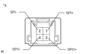
- INSPECT DCM (TELEMATICS TRANSCEIVER)
- Remove the DCM (telematics transceiver).
Refer to REMOVAL [12/2019 - 10/2022]
- Measure the resistance according to the value(s) in the table below.
*a Component without harness connected
(DCM (Telematics Transceiver))Standard Resistance
Tester Connection Condition Specified Condition 1 (SPI+) - 3 (SPO+) Always Below 1 Ω 2 (SPI-) - 4 (SPO-) Always Below 1 Ω 1 (SPI+) - 2 (SPI-) Always 10 kΩ or higher 3 (SPO+) - 4 (SPO-) Always 10 kΩ or higher 1 (SPI+) or 3 (SPO+) - Body ground Always 10 kΩ or higher 2 (SPI-) or 4 (SPO-) - Body ground Always 10 kΩ or higher Result
Proceed to OK NG
Result:
NG
REPLACE DCM (TELEMATICS TRANSCEIVER). Refer to REMOVAL [12/2019 - 10/2022]
Result:
OK
See step 6
- Remove the DCM (telematics transceiver).
- INSPECT FRONT NO. 1 SPEAKER ASSEMBLY
- Remove the front No. 1 speaker assembly.
Refer to REMOVAL [12/2019 - ]
- Inspect the front No. 1 speaker assembly.
Refer to INSPECTION [12/2019 - ]
Result
Proceed to OK NG
Result:
NG
REPLACE FRONT NO. 1 SPEAKER ASSEMBLY. Refer to REMOVAL [12/2019 - ]
Result:
OK
See step 7
- Remove the front No. 1 speaker assembly.
- REPLACE FRONT NO. 2 SPEAKER ASSEMBLY
- Remove the front No. 2 speaker assembly.
Refer to REMOVAL [12/2019 - ]
- Inspect the front No. 2 speaker assembly.
Refer to INSPECTION [12/2019 - ]
OK
Malfunction disappears.
Result
Proceed to OK NG
Result:
OK
END
Result:
NG
PROCEED TO NEXT SUSPECTED AREA SHOWN IN PROBLEM SYMPTOMS TABLE. Refer to PROBLEM SYMPTOMS TABLE [12/2019 - 10/2022]
- Remove the front No. 2 speaker assembly.
- CHECK HARNESS AND CONNECTOR (RADIO AND DISPLAY RECEIVER ASSEMBLY - REAR SPEAKER ASSEMBLY)
- Disconnect the H9 radio and display receiver assembly connector.
- Disconnect the K1 and K6 rear speaker assembly connectors.
- Measure the resistance according to the value (s) in the table below.
Standard Resistance
Tester Connection Condition Specified Condition H9-4 (RR+) - K1-1 Always Below 1 Ω H9-9 (RR-) - K1-2 Always Below 1 Ω H9-3 (RL+) - K6-1 Always Below 1 Ω H9-8 (RL-) - K6-2 Always Below 1 Ω H9-4 (RR+) or K1-1 - Body ground Always 10 kΩ or higher H9-9 (RR-) or K1-2 - Body ground Always 10 kΩ or higher H9-3 (RL+) or K6-1 - Body ground Always 10 kΩ or higher H9-8 (RL-) or K6-2 - Body ground Always 10 kΩ or higher Result
Proceed to OK NG
Result:
NG
REPAIR OR REPLACE HARNESS OR CONNECTOR
Result:
OK
See step 9
- INSPECT REAR SPEAKER ASSEMBLY
- Remove the rear speaker assembly.
Refer to REMOVAL [12/2019 - ]
- Inspect the rear speaker assembly.
Refer to INSPECTION [12/2019 - ]
Result
Proceed to OK NG
Result:
OK
PROCEED TO NEXT SUSPECTED AREA SHOWN IN PROBLEM SYMPTOMS TABLE. Refer to PROBLEM SYMPTOMS TABLE [12/2019 - 10/2022]
Result:
NG
REPLACE REAR SPEAKER ASSEMBLY. Refer to REMOVAL [12/2019 - ]
- Remove the rear speaker assembly.
- CHECK SPEAKER (OPERATION CHECK)
- Enter the "System Check Mode" screen. Refer to Check Speaker in Operation Check.
Refer to OPERATION CHECK [12/2019 - 10/2022]
- Perform the operation check above and determine the speaker that is not operating.
HINT:
If sound cannot be heard from any speaker, inspect all of them.
Result
Not Operating Speaker Proceed to Front No. 1 speaker assembly or front No. 3 speaker assembly A Front No. 2 speaker assembly B Rear speaker assembly C Rear No. 2 speaker assembly D Rear No. 3 speaker assembly E
Result:
B
See step 14
Result:
C
See step 16
Result:
D
See step 18
Result:
E
See step 20
Result:
A
See step 11
- Enter the "System Check Mode" screen. Refer to Check Speaker in Operation Check.
- CHECK HARNESS AND CONNECTOR (STEREO COMPONENT AMPLIFIER ASSEMBLY - FRONT NO. 1 SPEAKER ASSEMBLY - FRONT NO. 3 SPEAKER ASSEMBLY)
- Disconnect the M37 stereo component amplifier assembly connector.
- Disconnect the J1 and J17 front No. 1 speaker assembly connectors.
- Disconnect the H13 and H14 front No. 3 speaker assembly connectors.
- Measure the resistance according to the value (s) in the table below.
Standard Resistance
Tester Connection Condition Specified Condition M37-15 (FR+) - H13-4 (+) Always Below 1 Ω M37-30 (FR-) - H13-2 (-) Always Below 1 Ω M37-11 (FL+) - H14-4 (+) Always Below 1 Ω M37-26 (FL-) - H14-2 (-) Always Below 1 Ω J1-2 - H13-3 (+) Always Below 1 Ω J1-1 - H13-1 (-) Always Below 1 Ω J17-2 - H14-3 (+) Always Below 1 Ω J17-1 - H14-1 (-) Always Below 1 Ω M37-15 (FR+) or H13-4 (+) - Body ground Always 10 kΩ or higher M37-30 (FR-) or H13-2 (-) - Body ground Always 10 kΩ or higher M37-11 (FL+) or H14-4 (+) - Body ground Always 10 kΩ or higher M37-26 (FL-) or H14-2 (-) - Body ground Always 10 kΩ or higher J1-2 or H13-3 (+) - Body ground Always 10 kΩ or higher J1-1 or H13-1 (-) - Body ground Always 10 kΩ or higher J17-2 or H14-3 (+) - Body ground Always 10 kΩ or higher J17-1 or H14-1 (-) - Body ground Always 10 kΩ or higher Result
Proceed to OK NG
Result:
NG
REPAIR OR REPLACE HARNESS OR CONNECTOR
Result:
OK
See step 12
- INSPECT FRONT NO. 1 SPEAKER ASSEMBLY
- Remove the front No. 1 speaker assembly.
Refer to REMOVAL [12/2019 - ]
- Inspect the front No. 1 speaker assembly.
Refer to INSPECTION [12/2019 - ]
Result
Proceed to OK NG
Result:
NG
REPLACE FRONT NO. 1 SPEAKER ASSEMBLY. Refer to REMOVAL [12/2019 - ]
Result:
OK
See step 13
- Remove the front No. 1 speaker assembly.
- REPLACE FRONT NO. 3 SPEAKER ASSEMBLY
- Remove the front No. 3 speaker assembly.
Refer to REMOVAL [12/2019 - ]
- Inspect the front No. 3 speaker assembly.
Refer to INSPECTION [12/2019 - ]
OK
Malfunction disappears.
Result
Proceed to OK NG
Result:
OK
END
Result:
NG
PROCEED TO NEXT SUSPECTED AREA SHOWN IN PROBLEM SYMPTOMS TABLE. Refer to PROBLEM SYMPTOMS TABLE [12/2019 - 10/2022]
- Remove the front No. 3 speaker assembly.
- CHECK HARNESS AND CONNECTOR (STEREO COMPONENT AMPLIFIER ASSEMBLY - FRONT NO. 2 SPEAKER ASSEMBLY)
- Disconnect the M37 stereo component amplifier assembly connector.
- Disconnect the H72 and H74 front No. 2 speaker assembly connectors.
- Measure the resistance according to the value (s) in the table below.
Standard Resistance
Tester Connection Condition Specified Condition M37-14 (TWR+) - H72-2 (TWR+) Always Below 1 Ω M37-29 (TWR-) - H72-1 (TWR-) Always Below 1 Ω M37-13 (TWL+) - H74-2 (TWL+) Always Below 1 Ω M37-28 (TWL-) - H74-1 (TWL-) Always Below 1 Ω M37-14 (TWR+) or H72-2 (TWR+) - Body ground Always 10 kΩ or higher M37-29 (TWR-) or H72-1 (TWR-) - Body ground Always 10 kΩ or higher M37-13 (TWL+) or H74-2 (TWL+) - Body ground Always 10 kΩ or higher M37-28 (TWL-) or H74-1 (TWL-) - Body ground Always 10 kΩ or higher Result
Proceed to OK NG
Result:
NG
REPAIR OR REPLACE HARNESS OR CONNECTOR
Result:
OK
See step 15
- INSPECT FRONT NO. 2 SPEAKER ASSEMBLY
- Remove the front No. 2 speaker assembly.
Refer to REMOVAL [12/2019 - ]
- Inspect the front No. 2 speaker assembly.
Refer to INSPECTION [12/2019 - ]
Result
Proceed to OK NG
Result:
OK
PROCEED TO NEXT SUSPECTED AREA SHOWN IN PROBLEM SYMPTOMS TABLE. Refer to PROBLEM SYMPTOMS TABLE [12/2019 - 10/2022]
Result:
NG
REPLACE FRONT NO. 2 SPEAKER ASSEMBLY. Refer to REMOVAL [12/2019 - ]
- Remove the front No. 2 speaker assembly.
- CHECK HARNESS AND CONNECTOR (STEREO COMPONENT AMPLIFIER ASSEMBLY - REAR SPEAKER ASSEMBLY)
- Disconnect the M37 stereo component amplifier assembly connector.
- Disconnect the K1 and K6 rear speaker assembly connectors.
- Measure the resistance according to the value (s) in the table below.
Standard Resistance
Tester Connection Condition Specified Condition M37-12 (RR+) - K1-1 Always Below 1 Ω M37-27 (RR-) - K1-2 Always Below 1 Ω M37-4 (RL+) - K6-1 Always Below 1 Ω M37-19 (RL-) - K6-2 Always Below 1 Ω M37-12 (RR+) or K1-1 - Body ground Always 10 kΩ or higher M37-27 (RR-) or K1-2 - Body ground Always 10 kΩ or higher M37-4 (RL+) or K6-1 - Body ground Always 10 kΩ or higher M37-19 (RL-) or K6-2 - Body ground Always 10 kΩ or higher Result
Proceed to OK NG
Result:
NG
REPAIR OR REPLACE HARNESS OR CONNECTOR
Result:
OK
See step 17
- INSPECT REAR SPEAKER ASSEMBLY
- Remove the rear speaker assembly.
Refer to REMOVAL [12/2019 - ]
- Inspect the rear speaker assembly.
Refer to INSPECTION [12/2019 - ]
Result
Proceed to OK NG
Result:
OK
PROCEED TO NEXT SUSPECTED AREA SHOWN IN PROBLEM SYMPTOMS TABLE. Refer to PROBLEM SYMPTOMS TABLE [12/2019 - 10/2022]
Result:
NG
REPLACE REAR SPEAKER ASSEMBLY. Refer to REMOVAL [12/2019 - ]
- Remove the rear speaker assembly.
- CHECK HARNESS AND CONNECTOR (STEREO COMPONENT AMPLIFIER ASSEMBLY - REAR NO. 2 SPEAKER ASSEMBLY)
- Disconnect the M37 stereo component amplifier assembly connector.
- Disconnect the M36 rear No. 2 speaker assembly connector.
- Measure the resistance according to the value(s) in the table below.
Standard Resistance
Tester Connection Condition Specified Condition M37-8 (WF1+) - M36-4 (WF1+) Always Below 1 Ω M37-23 (WF1-) - M36-3 (WF1-) Always Below 1 Ω M37-7 (WF2+) - M36-2 (WF2+) Always Below 1 Ω M37-22 (WF2-) - M36-1 (WF2-) Always Below 1 Ω M37-8 (WF1+) or M36-4 (WF1+) - Body ground Always 10 kΩ or higher M37-23 (WF1-) or M36-3 (WF1-) - Body ground Always 10 kΩ or higher M37-7 (WF2+) or M36-2 (WF2+) - Body ground Always 10 kΩ or higher M37-22 (WF2-) or M36-1 (WF2-) - Body ground Always 10 kΩ or higher Result
Proceed to OK NG
Result:
NG
REPAIR OR REPLACE HARNESS OR CONNECTOR
Result:
OK
See step 19
- INSPECT REAR NO. 2 SPEAKER ASSEMBLY
- Remove the rear No. 2 speaker assembly.
Refer to REMOVAL [12/2019 - ]
- Inspect the rear No. 2 speaker assembly.
Refer to INSPECTION [12/2019 - ]
Result
Proceed to OK NG
Result:
OK
PROCEED TO NEXT SUSPECTED AREA SHOWN IN PROBLEM SYMPTOMS TABLE. Refer to PROBLEM SYMPTOMS TABLE [12/2019 - 10/2022]
Result:
NG
REPLACE REAR NO. 2 SPEAKER ASSEMBLY. Refer to REMOVAL [12/2019 - ]
- Remove the rear No. 2 speaker assembly.
- CHECK HARNESS AND CONNECTOR (STEREO COMPONENT AMPLIFIER ASSEMBLY - REAR NO. 3 SPEAKER ASSEMBLY)
- Disconnect the M37 stereo component amplifier assembly connector.
- Disconnect the W22 and W23 rear No. 3 speaker assembly connectors.
- Measure the resistance according to the value (s) in the table below.
Standard Resistance
Tester Connection Condition Specified Condition M37-9 (SR+) - W22-2 Always Below 1 Ω M37-24 (SR-) - W22-1 Always Below 1 Ω M37-5 (SL+) - W23-2 Always Below 1 Ω M37-20 (SL-) - W23-1 Always Below 1 Ω M37-9 (SR+) or W22-2 - Body ground Always 10 kΩ or higher M37-24 (SR-) or W22-1 - Body ground Always 10 kΩ or higher M37-5 (SL+) or W23-2 - Body ground Always 10 kΩ or higher M37-20 (SL-) or W23-1 - Body ground Always 10 kΩ or higher Result
Proceed to OK NG
Result:
NG
REPAIR OR REPLACE HARNESS OR CONNECTOR
Result:
OK
See step 21
- INSPECT REAR NO. 3 SPEAKER ASSEMBLY
- Remove the rear No. 3 speaker assembly.
Refer to REMOVAL [12/2019 - ]
- Inspect the rear No. 3 speaker assembly.
Refer to INSPECTION [12/2019 - ]
Result
Proceed to OK NG
Result:
OK
PROCEED TO NEXT SUSPECTED AREA SHOWN IN PROBLEM SYMPTOMS TABLE. Refer to PROBLEM SYMPTOMS TABLE [12/2019 - 10/2022]
Result:
NG
REPLACE REAR NO. 3 SPEAKER ASSEMBLY. Refer to REMOVAL [12/2019 - ]
- Remove the rear No. 3 speaker assembly.