Speaker Circuit [10/2022 - ]: Procedure
- CHECK MODEL
- Choose the model to be inspected.
Result
Result Proceed to w/ DCM (Telematics Transceiver) A w/o DCM (Telematics Transceiver) B
Result:
B
See step 9
Result:
A
See step 2
- Choose the model to be inspected.
- CHECK SPEAKER (OPERATION CHECK)
- Enter diagnostic mode.
Refer to DIAGNOSIS SYSTEM [10/2022 - ]
- Select "Failure Diagnosis" from the "Service Menu" screen.
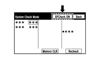
- Select "System Check" from the "Failure Diagnosis" screen.
- Select "SPCheck ON" from the "System Check Mode" screen and perform speaker check.
OK
Each speaker outputs sound from the selected audio source properly.
Result
Result Proceed to Front No. 1 speaker assembly or front No. 2 speaker assembly does not output sound A Rear speaker assembly does not output sound B
Result:
B
See step 7
Result:
A
See step 3
- Enter diagnostic mode.
- CHECK HARNESS AND CONNECTOR (SPEAKER CIRCUIT)
- Disconnect the H9 radio and display receiver assembly connector.
- Disconnect the J1 and J17 front No. 1 speaker assembly connectors.
- Disconnect the H117 and H73 front No. 2 speaker assembly connectors.
- Disconnect the H12 DCM (telematics transceiver) connector.
- Measure the resistance according to the value(s) in the table below.
Standard Resistance
Tester Connection Condition Specified Condition H9-2 (FL+) - H73-4 (TWL+) Always Below 1 Ω H9-7 (FL-) - H73-2 (TWL-) Always Below 1 Ω H9-1 (FR+) - H12-1 (SPI+) Always Below 1 Ω H9-6 (FR-) - H12-2 (SPI-) Always Below 1 Ω H12-3 (SPO+) - H117-4 (+TW) Always Below 1 Ω H12-4 (SPO-) - H117-2 (-TW) Always Below 1 Ω J17-2 - H73-3 (+) Always Below 1 Ω J17-1 - H73-1 (-) Always Below 1 Ω J1-2 - H117-3 (+) Always Below 1 Ω J1-1 - H117-1 (-) Always Below 1 Ω H9-2 (FL+) or H73-4 (TWL+) - Body ground Always 10 kΩ or higher H9-7 (FL-) or H73-2 (TWL-) - Body ground Always 10 kΩ or higher H9-1 (FR+) or H12-1 (SPI+) - Body ground Always 10 kΩ or higher H9-6 (FR-) or H12-2 (SPI-) - Body ground Always 10 kΩ or higher H12-3 (SPO+) or H117-4 (+TW) - Body ground Always 10 kΩ or higher H12-4 (SPO-) or H117-2 (-TW) - Body ground Always 10 kΩ or higher J17-2 or H73-3 (+) - Body ground Always 10 kΩ or higher J17-1 or H73-1 (-) - Body ground Always 10 kΩ or higher J1-2 or H117-3 (+) - Body ground Always 10 kΩ or higher J1-1 or H117-1 (-) - Body ground Always 10 kΩ or higher Result
Proceed to OK NG
Result:
NG
REPAIR OR REPLACE HARNESS OR CONNECTOR
Result:
OK
See step 4
- INSPECT DCM (TELEMATICS TRANSCEIVER)
- Remove the DCM (telematics transceiver).
Refer to REMOVAL [10/2022 - 11/2023] , or refer to REMOVAL [11/2023 - ]
- Measure the resistance according to the value(s) in the table below.
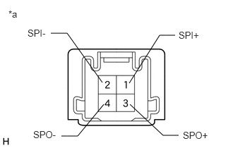
*a Component without harness connected
(DCM (Telematics Transceiver))Standard Resistance
Tester Connection Condition Specified Condition 1 (SPI+) - 3 (SPO+) Always Below 1 Ω 2 (SPI-) - 4 (SPO-) Always Below 1 Ω 1 (SPI+) - 2 (SPI-) Always 10 kΩ or higher 3 (SPO+) - 4 (SPO-) Always 10 kΩ or higher 1 (SPI+) or 3 (SPO+) - Body ground Always 10 kΩ or higher 2 (SPI-) or 4 (SPO-) - Body ground Always 10 kΩ or higher Result
Proceed to OK NG
Result:
NG
REPLACE DCM (TELEMATICS TRANSCEIVER). Refer to REMOVAL [10/2022 - 11/2023] , or refer to REMOVAL [11/2023 - ]
Result:
OK
See step 5
- Remove the DCM (telematics transceiver).
- INSPECT FRONT NO. 1 SPEAKER ASSEMBLY
Refer to INSPECTION [12/2019 - ]
Result
Proceed to OK NG Result:
NG
REPLACE FRONT NO. 1 SPEAKER ASSEMBLY. Refer to REMOVAL [12/2019 - ]
Result:
OK
See step 6
- REPLACE FRONT NO. 2 SPEAKER ASSEMBLY
- Replace the front No. 2 speaker assembly with a new or known good one.
Refer to REMOVAL [12/2019 - ]
- Check if the malfunction disappears.
Result
Result Proceed to Malfunction disappears A Malfunction occurs B
Result:
A
END (FRONT NO. 2 SPEAKER ASSEMBLY IS DEFECTIVE)
Result:
B
REPLACE RADIO AND DISPLAY RECEIVER ASSEMBLY. Refer to REMOVAL [10/2022 - 11/2023] , or refer to REMOVAL [11/2023 - ]
- Replace the front No. 2 speaker assembly with a new or known good one.
- CHECK HARNESS AND CONNECTOR (SPEAKER CIRCUIT)
- Disconnect the H9 radio and display receiver assembly connector.
- Disconnect the K1 and K6 rear speaker assembly connectors.
- Measure the resistance according to the value(s) in the table below.
Standard Resistance
Tester Connection Condition Specified Condition H9-3 (RL+) - K6-2 Always Below 1 Ω H9-8 (RL-) - K6-1 Always Below 1 Ω H9-4 (RR+) - K1-2 Always Below 1 Ω H9-9 (RR-) - K1-1 Always Below 1 Ω H9-3 (RL+) or K6-2 - Body ground Always 10 kΩ or higher H9-8 (RL-) or K6-1 - Body ground Always 10 kΩ or higher H9-4 (RR+) or K1-2 - Body ground Always 10 kΩ or higher H9-9 (RR-) or K1-1 - Body ground Always 10 kΩ or higher Result
Proceed to OK NG
Result:
NG
REPAIR OR REPLACE HARNESS OR CONNECTOR
Result:
OK
See step 8
- INSPECT REAR SPEAKER ASSEMBLY
Refer to INSPECTION [12/2019 - ]
Result
Proceed to OK NG Result:
OK
REPLACE RADIO AND DISPLAY RECEIVER ASSEMBLY. Refer to REMOVAL [10/2022 - 11/2023] , or refer to REMOVAL [11/2023 - ]
Result:
NG
REPLACE REAR SPEAKER ASSEMBLY. Refer to REMOVAL [12/2019 - ]
- CHECK SPEAKER (OPERATION CHECK)
- Enter diagnostic mode.
Refer to DIAGNOSIS SYSTEM [10/2022 - ]
- Select "Failure Diagnosis" from the "Service Menu" screen.
- Select "System Check" from the "Failure Diagnosis" screen.
- Select "SPCheck ON" from the "System Check Mode" screen and perform speaker check.
OK
Each speaker outputs sound from the selected audio source properly.
Result
Not Operating Speaker Proceed to Front No. 1 speaker assembly or front No. 2 speaker assembly A Rear speaker assembly B
Result:
B
See step 13
Result:
A
See step 10
- Enter diagnostic mode.
- CHECK HARNESS AND CONNECTOR (RADIO AND DISPLAY RECEIVER ASSEMBLY - FRONT NO. 1 SPEAKER ASSEMBLY - FRONT NO. 2 SPEAKER ASSEMBLY)
- Disconnect the H9 radio and display receiver assembly connector.
- Disconnect the J1 and J17 front No. 1 speaker assembly connectors.
- Disconnect the H117 and H73 front No. 2 speaker assembly connectors.
- Measure the resistance according to the value (s) in the table below.
Standard Resistance
Tester Connection Condition Specified Condition H9-1 (FR+) - H117-4 (+TW) Always Below 1 Ω H9-6 (FR-) - H117-2 (-TW) Always Below 1 Ω H9-2 (FL+) - H73-4 (TWL+) Always Below 1 Ω H9-7 (FL-) - H73-2 (TWL-) Always Below 1 Ω J1-2 - H117-3 (+) Always Below 1 Ω J1-1 - H117-1 (-) Always Below 1 Ω J17-2 - H73-3 (+) Always Below 1 Ω J17-1 - H73-1 (-) Always Below 1 Ω H9-1 (FR+) or H117-4 (+TW) - Body ground Always 10 kΩ or higher H9-6 (FR-) or H117-2 (-TW) - Body ground Always 10 kΩ or higher H9-2 (FL+) or H73-4 (TWL+) - Body ground Always 10 kΩ or higher H9-7 (FL-) or H73-2 (TWL-) - Body ground Always 10 kΩ or higher J1-2 or H117-3 (+) - Body ground Always 10 kΩ or higher J1-1 or H117-1 (-) - Body ground Always 10 kΩ or higher J17-2 or H73-3 (+) - Body ground Always 10 kΩ or higher J17-1 or H73-1 (-) - Body ground Always 10 kΩ or higher Result
Proceed to OK NG
Result:
NG
REPAIR OR REPLACE HARNESS OR CONNECTOR
Result:
OK
See step 11
- INSPECT FRONT NO. 1 SPEAKER ASSEMBLY
Refer to INSPECTION [12/2019 - ]
Result
Proceed to OK NG Result:
NG
REPLACE FRONT NO. 1 SPEAKER ASSEMBLY. Refer to REMOVAL [12/2019 - ]
Result:
OK
See step 12
- REPLACE FRONT NO. 2 SPEAKER ASSEMBLY
Refer to REMOVAL [12/2019 - ]
OK
Malfunction disappears.
Result
Proceed to OK NG Result:
OK
END
Result:
NG
REPLACE RADIO AND DISPLAY RECEIVER ASSEMBLY. Refer to REMOVAL [10/2022 - 11/2023] , or refer to REMOVAL [11/2023 - ]
- CHECK HARNESS AND CONNECTOR (RADIO AND DISPLAY RECEIVER ASSEMBLY - REAR SPEAKER ASSEMBLY)
- Disconnect the H9 radio and display receiver assembly connector.
- Disconnect the K1 and K6 rear speaker assembly connectors.
- Measure the resistance according to the value (s) in the table below.
Standard Resistance
Tester Connection Condition Specified Condition H9-4 (RR+) - K1-2 Always Below 1 Ω H9-9 (RR-) - K1-1 Always Below 1 Ω H9-3 (RL+) - K6-2 Always Below 1 Ω H9-8 (RL-) - K6-1 Always Below 1 Ω H9-4 (RR+) or K1-2 - Body ground Always 10 kΩ or higher H9-9 (RR-) or K1-1 - Body ground Always 10 kΩ or higher H9-3 (RL+) or K6-2 - Body ground Always 10 kΩ or higher H9-8 (RL-) or K6-1 - Body ground Always 10 kΩ or higher Result
Proceed to OK NG
Result:
NG
REPAIR OR REPLACE HARNESS OR CONNECTOR
Result:
OK
See step 14
- INSPECT REAR SPEAKER ASSEMBLY
Refer to INSPECTION [12/2019 - ]
Result
Proceed to OK NG Result:
OK
REPLACE RADIO AND DISPLAY RECEIVER ASSEMBLY. Refer to REMOVAL [10/2022 - 11/2023] , or refer to REMOVAL [11/2023 - ]
Result:
NG
REPLACE REAR SPEAKER ASSEMBLY. Refer to REMOVAL [12/2019 - ]