AVC-LAN Circuit [10/2022 - ]: Procedure
- DEALER INSTALLED OPTIONAL DEVICES (AVC-LAN COMPATIBLE DEVICES)
- Disconnect the connector of each dealer installed optional device (AVC-LAN compatible device) and check if the malfunction continues.
Result
Result Proceed to No dealer installed optional devices are installed A The malfunction reoccurs The system returns to normal B
Result:
B
REPLACE THE DEVICE (OR WIRE HARNESS)
Result:
A
See step 2
- Disconnect the connector of each dealer installed optional device (AVC-LAN compatible device) and check if the malfunction continues.
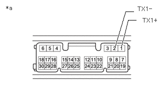
- INSPECT RADIO AND DISPLAY RECEIVER ASSEMBLY
- Remove the radio and display receiver assembly.
- Measure the resistance according to the value(s) in the table below.
Standard Resistance
Tester Connection Condition Specified Condition 1 (TX1+) - 2 (TX1-) Always 60 to 80 Ω *a Component without harness connected
(Radio and Display Receiver Assembly)Result
Proceed to OK NG
Result:
NG
REPLACE RADIO AND DISPLAY RECEIVER ASSEMBLY. Refer to REMOVAL [10/2022 - 11/2023] , or refer to REMOVAL [11/2023 - ]
Result:
OK
See step 3
- CHECK HARNESS AND CONNECTOR (AVC-LAN CIRCUIT)
- Disconnect the H108 radio and display receiver assembly connector.
- Disconnect the M38 stereo component amplifier assembly connector.
- Measure the resistance according to the value(s) in the table below.
Standard Resistance
Tester Connection Condition Specified Condition M38-8 (TX+) - H108-1 (TX1+) Always Below 1 Ω M38-7 (TX-) - H108-2 (TX1-) Always Below 1 Ω M38-8 (TX+) - Body ground Always 10 kΩ or higher M38-7 (TX-) - Body ground Always 10 kΩ or higher Result
Proceed to OK NG
Result:
NG
REPAIR OR REPLACE HARNESS OR CONNECTOR
Result:
OK
See step 4
- INSPECT RADIO AND DISPLAY RECEIVER ASSEMBLY (AVC-LAN VOLTAGE)
- Measure the voltage according to the value(s) in the table below.
Standard Voltage
Tester Connection Switch Condition Specified Condition H108-1 (TX1+) - H108-2 (TX1-) Ignition Switch ACC Approximately 0 V H108-1 (TX1+) - Body ground Ignition Switch ACC Approximately 2.5 V H108-2 (TX1-) - Body ground Ignition Switch ACC Approximately 2.5 V Result
Proceed to OK NG
Result:
OK
REPLACE RADIO AND DISPLAY RECEIVER ASSEMBLY. Refer to REMOVAL [10/2022 - 11/2023] , or refer to REMOVAL [11/2023 - ]
Result:
NG
CHECK HARNESS OR CONNECTOR
- Measure the voltage according to the value(s) in the table below.