DTC B158F: AV Signal Stoppage (Low Battery Voltage) [12/2019 - 10/2022]: Procedure
- CHECK VEHICLE SIGNAL (OPERATION CHECK)
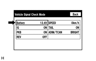
- Enter the "Vehicle Signal Check Mode" screen. Refer to Check Vehicle Signal in Operation Check.
Refer to OPERATION CHECK [12/2019 - 10/2022]
- Measure the auxiliary battery voltage.
Standard Voltage
11 to 14 V (w/o Stop and Start System)
10.5 to 16 V (w/ Stop and Start System)
HINT:
This display is updated once per second.
Result
Proceed to OK NG
Result:
NG
See step 3
Result:
OK
See step 2
- Enter the "Vehicle Signal Check Mode" screen. Refer to Check Vehicle Signal in Operation Check.
- CHECK DTC
- Clear the DTCs.
Body Electrical > Navigation System > Clear DTCs
- Recheck for DTCs and check that no DTCs are output.
Body Electrical > Navigation System > Trouble Codes
OK
No DTCs are output.
Result
Proceed to OK NG
Result:
OK
END
Result:
NG
REPLACE RADIO AND DISPLAY RECEIVER ASSEMBLY. Refer to REMOVAL [12/2019 - 10/2022]
- Clear the DTCs.
- CHECK HARNESS AND CONNECTOR (RADIO AND DISPLAY RECEIVER ASSEMBLY POWER SOURCE)
- Disconnect the H1 radio and display receiver assembly connector.
- Measure the voltage according to the value(s) in the table below.
Standard Voltage
Tester Connection Condition Specified Condition H1-4 (+B1) - Body ground*1 Ignition switch off 11 to 14 V H1-4 (+B1) - Body ground*2 Always 11 to 14 V*3
10.5 to 16 V*4- *1: for HV Model
- *2: for Gasoline Model
- *3: w/o Stop and Start System
- *4: w/ Stop and Start System
Result
Result Proceed to OK A NG (w/o Stop and Start System) B NG (w/ Stop and Start System) C
Result:
A
REPLACE RADIO AND DISPLAY RECEIVER ASSEMBLY. Refer to REMOVAL [12/2019 - 10/2022]
Result:
B
REPAIR OR REPLACE HARNESS OR CONNECTOR
Result:
C
GO TO STOP AND START SYSTEM. Refer to HOW TO PROCEED WITH TROUBLESHOOTING [12/2019 - 10/2022]