DTC B15FE-11: XM Tuner Antenna Circuit Short to Ground; DTC B15FE-13: XM Tuner Antenna Circuit Open [11/2024 - ]: Procedure
- CHECK CONNECTION OF ANTENNA CABLE
- Check if the roof antenna assembly cable is securely connected to the radio and display receiver assembly.
OK
Roof antenna assembly cable is securely connected.
Result
Proceed to OK NG
Result:
NG
SECURELY CONNECT ROOF ANTENNA ASSEMBLY
Result:
OK
See step 2
- Check if the roof antenna assembly cable is securely connected to the radio and display receiver assembly.
- CLEAR DTC
Result:
NEXT
See step 3
- CHECK FOR DTC
- Recheck for DTCs and check that no DTCs are output.
Body Electrical > Navigation System > Trouble Codes
Result
Result Proceed to DTCs are not output A DTCs are output B
Result:
A
USE SIMULATION METHOD TO CHECK
Refer to HOW TO PROCEED WITH TROUBLESHOOTING [12/2019 - ]
Result:
B
See step 4
- Recheck for DTCs and check that no DTCs are output.
- CHECK NO. 4 ANTENNA CORD SUB-ASSEMBLY
Pre-procedure1
- Disconnect the antenna connector from the roof antenna assembly.
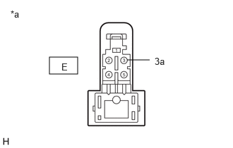
*a Front view of wire harness connector
(to Roof antenna assembly) - Disconnect the antenna connector from the No. 3 antenna cord sub-assembly.
*a Front view of wire harness connector
(to No. 3 antenna cord sub-assembly)Procedure1
- Measure the resistance according to the value(s) in the table below.
Standard Resistance
Tester Connection Condition Specified Condition E-3 - D-5 Always Below 1 Ω E-3a - D-5a Always Below 1 Ω E-3 - Body ground Always 10 kΩ or higher Result
Proceed to OK NG Post-procedure1
- None
Result:
NG
REPLACE NO. 4 ANTENNA CORD SUB-ASSEMBLY
Refer to REMOVAL [11/2024 - ]
Result:
OK
See step 5
- Disconnect the antenna connector from the roof antenna assembly.
- CHECK NO. 3 ANTENNA CORD SUB-ASSEMBLY
Pre-procedure1
- Disconnect the antenna connector from the No. 4 antenna cord sub-assembly.
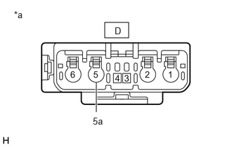
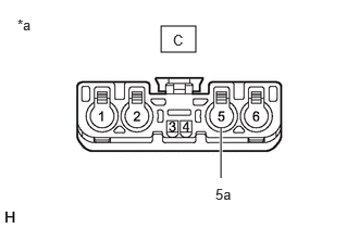
*a Front view of wire harness connector
(to No. 4 Antenna Cord Sub-assembly) - Disconnect the antenna connector from the antenna cord sub-assembly.
*a Front view of wire harness connector
(to Antenna Cord Sub-assembly)Procedure1
- Measure the resistance according to the value(s) in the table below.
Standard Resistance
Tester Connection Condition Specified Condition B-5 - C-5 Always Below 1 Ω B-5a - C-5a Always Below 1 Ω C-5 - Body ground Always 10 kΩ or higher Result
Proceed to OK NG Post-procedure1
- None
Result:
NG
REPLACE NO. 3 ANTENNA CORD SUB-ASSEMBLY
Refer to REMOVAL [11/2024 - ]
Result:
OK
See step 6
- Disconnect the antenna connector from the No. 4 antenna cord sub-assembly.
- CHECK ANTENNA CORD SUB-ASSEMBLY
Pre-procedure1
- Disconnect the antenna connector from the No. 3 antenna cord sub-assembly.
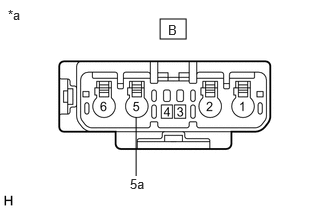
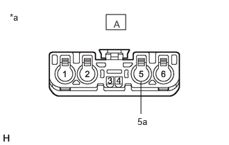
*a Front view of wire harness connector
(to No. 3 antenna cord sub-assembly) - Disconnect the antenna connector from the radio and display receiver assembly.
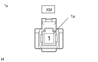
*a Front view of wire harness connector
(to Radio and Display Receiver Assembly)Procedure1
- Measure the resistance according to the value(s) in the table below.
Standard Resistance
Tester Connection Condition Specified Condition A-5 - XM-1 (XM) Always Below 1 Ω A-5a - XM-1a Always Below 1 Ω A-5 - Body ground Always 10 kΩ or higher Result
Proceed to OK NG Post-procedure1
- None
Result:
NG
REPLACE ANTENNA CORD SUB-ASSEMBLY
Refer to REMOVAL [11/2024 - ]
Result:
OK
See step 7
- Disconnect the antenna connector from the No. 3 antenna cord sub-assembly.
- REPLACE ROOF ANTENNA ASSEMBLY
Pre-procedure1
- Replace the rood antenna assembly with a new or known good one.
Refer to REMOVAL [12/2019 - ]
- Clear the DTCs.
Body Electrical > Navigation System > Clear DTCs
Procedure1
- Check for DTCs.
Body Electrical > Navigation System > Trouble Codes
Result
Result Proceed to DTCs are not output A DTCs are output B Post-procedure1
- None
Result:
A
END (ROOF ANTENNA ASSEMBLY IS DEFECTIVE)
Result:
B
REPLACE RADIO AND DISPLAY RECEIVER ASSEMBLY
Refer to REMOVAL [11/2023 - ]
- Replace the rood antenna assembly with a new or known good one.