DTC B2282-31: Vehicle Speed Signal Circuit Open [10/2022 - ]: Procedure
- CHECK VEHICLE CONTROL HISTORY (RoB)
- Check vehicle control history (RoB)
- Using the GTS, check for vehicle control history (RoB).
Body Electrical > Navigation System > Utility
Tester Display Vehicle Control History (RoB)
Result
Result Proceed to Vehicle control history (RoB) X8023 is output A Vehicle control history (RoB) is not output B - Using the GTS, check for vehicle control history (RoB).
Result:
B
See step 4
Result:
A
See step 2
- Check vehicle control history (RoB)
- CHECK OPTIONAL COMPONENTS
- Check that optional components are not installed.
Result
Result Proceed to Optional components are installed A Optional components are not installed B
Result:
B
See step 4
Result:
A
See step 3
- Check that optional components are not installed.
- REMOVE OPTIONAL COMPONENTS
Result:
NEXT
See step 4
- CHECK VEHICLE SENSOR (SYSTEM SENSORS CHECK)
HINT:
For enter diagnostic mode and screen transition. Refer to DIAGNOSIS SYSTEM [10/2022 - ]
- Enter diagnostic mode.
- Enter diagnostic mode.
- Select "Function Check/Setting" from the "Service Menu" screen.
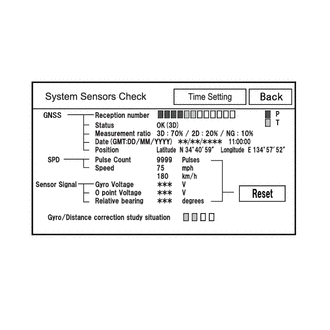
- Select "System Sensors Check" from the "Function Check/Setting I" screen.
- System sensors check
- Drive the vehicle and confirm that the displayed Speed changes in accordance with the vehicle driving condition.
Result
Result Proceed to Speed changes A Speed does not change B
Result:
A
REPLACE RADIO AND DISPLAY RECEIVER ASSEMBLY
Refer to REMOVAL [10/2022 - 11/2023] , or refer to REMOVAL [11/2023 - ]
Result:
B
See step 5
- Enter diagnostic mode.
- CHECK HARNESS AND CONNECTOR (COMBINATION METER ASSEMBLY - RADIO AND DISPLAY RECEIVER ASSEMBLY)
- Disconnect the H21*2, H112*1 combination meter assembly connector.
- Disconnect the H107 radio and display receiver assembly connector.
- Measure the resistance according to the value(s) in the table below.
Standard Resistance
Tester Connection Condition Specified Condition H21-6 (+S) - H107-8 (SPD)*2 Always Below 1 Ω H112-8 (+S) - H107-8 (SPD)*1 Always Below 1 Ω H21-6 (+S) or H107-8 (SPD) - Body ground*2 Always 10 kΩ or higher H112-8 (+S) or H107-8 (SPD) - Body ground*1 Always 10 kΩ or higher - *1: for 12.3 Inch Display
*2: except 12.3 Inch Display
Result
Proceed to OK NG - *1: for 12.3 Inch Display
Result:
OK
GO TO METER / GAUGE SYSTEM
except 12.3 Inch Display: Refer to Speed Signal Circuit [10/2022 - 11/2023] , or refer to Speed Signal Circuit [11/2023 - ]
for 12.3 Inch Display: Refer to Speed Signal Circuit [10/2022 - 11/2023] , or refer to Speed Signal Circuit [11/2023 - ]
Result:
NG
REPAIR OR REPLACE HARNESS OR CONNECTOR