Installation [12/2019 - 11/2024]: Procedure
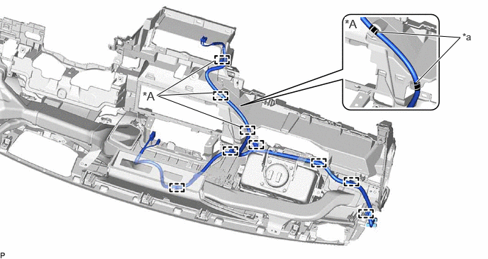
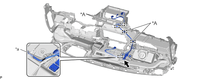
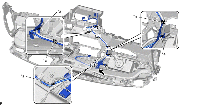
- INSTALL NO. 4 ANTENNA CORD SUB-ASSEMBLY
- Engage each clamp to install the No. 4 antenna cord sub-assembly.
- Connect the connector.
- INSTALL NO. 3 ANTENNA CORD SUB-ASSEMBLY (for Normal Roof)
HINT:
Butyl tape and adhesive tape are not available as supply parts. If these pieces of tape still have enough adhesion to secure the No. 3 antenna cord sub-assembly to the roof headlining assembly, reuse them. If the adhesive tape and/or the butyl tape is no longer sticky, apply new tape following the procedure below.
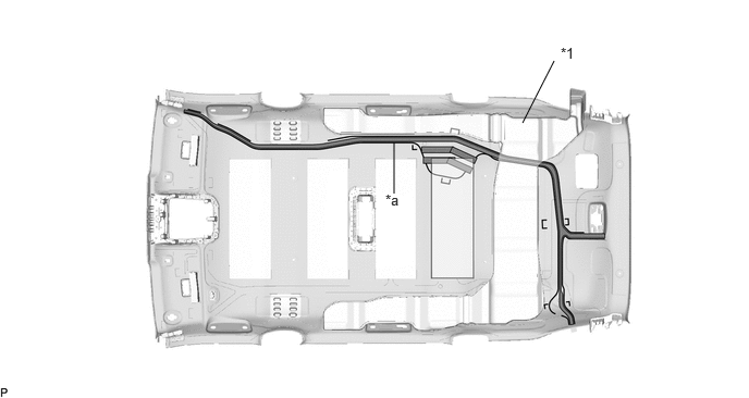
- Apply new butyl tape.
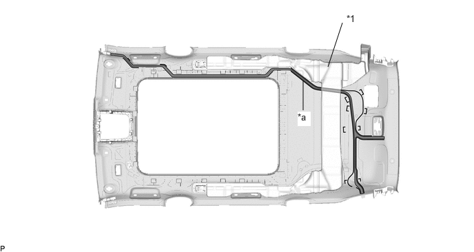
*1 Rear Roof Air Duct - - *a Marking - - 
Butyl tape - - - Remove the old butyl tape from the roof headlining assembly.
- Prepare an appropriate amount of new butyl tape.
HINT:
Be careful not to touch the adhesive surface.
- Apply the butyl tape to the roof headlining assembly while aligning the tape with the markings on the roof headlining assembly.
HINT:
Slide the butyl tape under the rear roof air duct then press it to attach it.
- Peel off the release paper from the butyl tape.
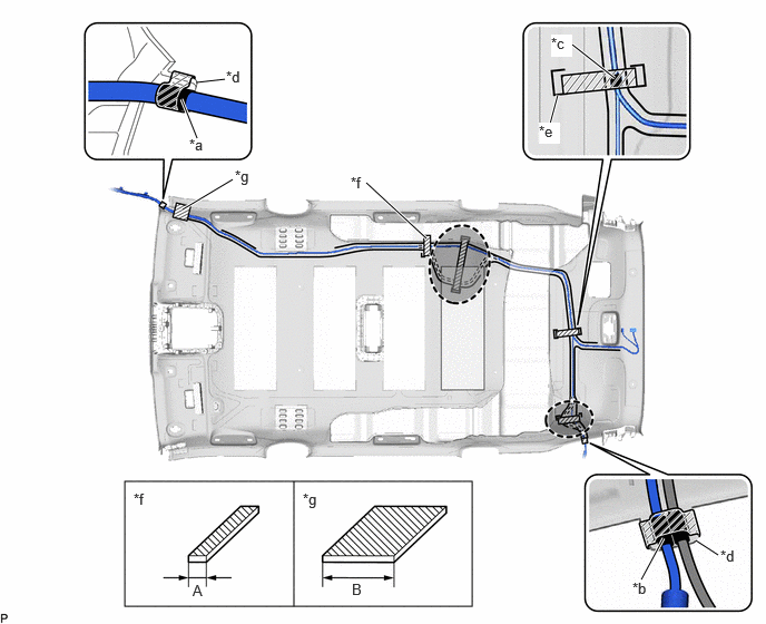
- Align the marking tape (A) on the No. 3 antenna cord sub-assembly with the protrusion on the front of the roof headlining assembly and wrap tape around the No. 3 antenna cord sub-assembly and protrusion of the roof headlining assembly.
*a Marking Tape (A) *b Marking Tape (B) *c Marking Tape (C) *d Protrusion *e Marking *f Adhesive Tape Size (A) *g Adhesive Tape Size (B) - - 
Adhesive Tape 
Adjustment Area Adhesive Tape Size
Area Dimension Area Dimension A 20 mm (0.787 in.) B 80 mm (3.15 in.) - Using wire, pass the No. 3 antenna cord sub-assembly between the rear roof air duct and roof headlining assembly.
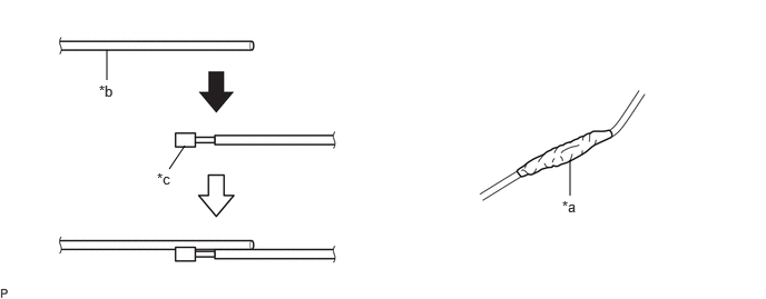
- Secure the wire with a diameter of 2.0 mm (0.0787 in.) to the No. 3 antenna cord sub-assembly with vinyl tape as shown in the illustration.
*a Vinyl Tape *b Wire *c Connector - - NOTE:Make sure that the wire is secured with vinyl tape to prevent the wire from separating from the No. 3 antenna cord sub-assembly when removing it.
HINT:
As the No. 3 antenna cord sub-assembly is likely to be caught in the narrow areas inside the roof headlining assembly, make sure to align in a straight line and cover the edges of the connectors with vinyl tape.
- Secure the wire with a diameter of 2.0 mm (0.0787 in.) to the No. 3 antenna cord sub-assembly with vinyl tape as shown in the illustration.
- Align the marking tape (B) on the No. 3 antenna cord sub-assembly with the protrusion on the rear of the roof headlining assembly and wrap tape around the No. 3 antenna cord sub-assembly and protrusion of the roof headlining assembly.
- Align the marking tape (C) on the No. 3 antenna cord sub-assembly with the marking on the roof headlining assembly and secure the No. 3 antenna cord sub-assembly with the adhesive tape as shown in the illustration.
- Install the No. 3 antenna cord sub-assembly to the roof headlining assembly.NOTE:
- Make sure that there are no gaps between the roof headlining assembly and No. 3 antenna cord sub-assembly, and that the No. 3 antenna cord sub-assembly is not twisted.
- Make sure the No. 3 antenna cord assembly is securely installed. If any part of the No. 3 antenna cord sub-assembly is loose, it will cause an abnormal noise.
HINT:
Secure the extra length of the No. 3 antenna cord sub-assembly in the adjustment area.
- Apply the adhesive tape as shown in the illustration to secure the No. 3 antenna cord sub-assembly.
- Apply new butyl tape.
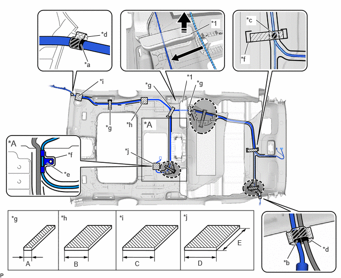
- INSTALL NO. 3 ANTENNA CORD SUB-ASSEMBLY (for Moon Roof)
HINT:
Butyl tape and adhesive tape are not available as supply parts. If these pieces of tape still have enough adhesion to secure the No. 3 antenna cord sub-assembly to the roof headlining assembly, reuse them. If the adhesive tape and/or the butyl tape is no longer sticky, apply new tape following the procedure below.
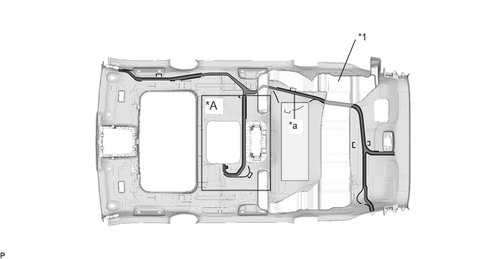
- Apply new butyl tape.
*A w/ Rear Seat Entertainment System - - *1 Rear Roof Air Duct - - *a Marking - - Butyl tape - - - Remove the old butyl tape from the roof headlining assembly.
- Prepare an appropriate amount of new butyl tape.
HINT:
Be careful not to touch the adhesive surface.
- Apply the butyl tape to the roof headlining assembly while aligning the tape with the markings on the roof headlining assembly.
HINT:
Slide the butyl tape under the rear roof air duct then press it to attach it.
- Peel off the release paper from the butyl tape.
- Align the marking tape (A) on the No. 3 antenna cord sub-assembly with the protrusion on the front of the roof headlining assembly and wrap tape around the No. 3 antenna cord sub-assembly and protrusion of the roof headlining assembly.
*A w/ Rear Seat Entertainment System - - *1 Rear Roof Air Duct - - *a Marking Tape (A) *b Marking Tape (B) *c Marking Tape (C) *d Protrusion *e Clamp *f Marking *g Adhesive Tape Size (A) *h Adhesive Tape Size (B) *i Adhesive Tape Size (C) *j Adhesive Tape Size (D) 
Lift up in this Direction Adjustment Area Adhesive Tape - - Adhesive Tape Size
Area Dimension Area Dimension A 20 mm (0.787 in.) B 60 mm (2.36 in.) C 80 mm (3.15 in.) D 80 mm (3.15 in.) E 100 mm (3.94 in.) - - - While lifting the rear roof air duct as shown in the illustration, pass the No. 3 antenna cord sub-assembly through.
HINT:
Lift up the rear roof air duct to the extent that the No. 3 antenna cord sub-assembly can be passed through.
- Using wire, pass the No. 3 antenna cord sub-assembly between the rear roof air duct and roof headlining assembly.
- Secure the wire with a diameter of 2.0 mm (0.0787 in.) to the No. 3 antenna cord sub-assembly with vinyl tape as shown in the illustration.
*a Vinyl Tape *b Wire *c Connector - - NOTE:Make sure that the wire is secured with vinyl tape to prevent the wire from separating from the No. 3 antenna cord sub-assembly when removing it.
HINT:
As the No. 3 antenna cord sub-assembly is likely to be caught in the narrow areas inside the roof headlining assembly, make sure to align in a straight line and cover the edges of the connectors with vinyl tape.
- Secure the wire with a diameter of 2.0 mm (0.0787 in.) to the No. 3 antenna cord sub-assembly with vinyl tape as shown in the illustration.
- Align the marking tape (B) on the No. 3 antenna cord sub-assembly with the protrusion on the rear of the roof headlining assembly and wrap tape around the No. 3 antenna cord sub-assembly and protrusion of the roof headlining assembly.
- Align the marking tape (C) on the No. 3 antenna cord sub-assembly with the marking on the roof headlining assembly and secure the No. 3 antenna cord sub-assembly with the adhesive tape as shown in the illustration.
- w/ Rear Seat Entertainment System:
- Align the clamp on the No. 3 antenna cord sub-assembly with the marking on the roof headlining assembly.
- Apply hot-melt glue, to secure the clamp on the No. 3 antenna cord sub-assembly as shown in the illustration.
- Install the No. 3 antenna cord sub-assembly to the roof headlining assembly.NOTE:
- Make sure that there are no gaps between the roof headlining assembly and No. 3 antenna cord sub-assembly, and that the No. 3 antenna cord sub-assembly is not twisted.
- Make sure the No. 3 antenna cord assembly is securely installed. If any part of the No. 3 antenna cord sub-assembly is loose, it will cause an abnormal noise.
HINT:
Secure the extra length of the No. 3 antenna cord sub-assembly in the adjustment area.
- Apply the adhesive tape as shown in the illustration to secure the No. 3 antenna cord sub-assembly.
- Apply new butyl tape.
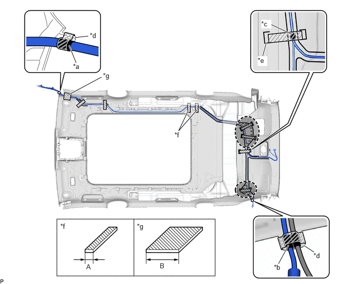
- INSTALL NO. 3 ANTENNA CORD SUB-ASSEMBLY (for Panoramic Moon Roof)
HINT:
Butyl tape and adhesive tape are not available as supply parts. If these pieces of tape still have enough adhesion to secure the No. 3 antenna cord sub-assembly to the roof headlining assembly, reuse them. If the adhesive tape and/or the butyl tape is no longer sticky, apply new tape following the procedure below.
- Apply new butyl tape.
*1 Rear Roof Air Duct - - *a Marking - - Butyl tape - - - Remove the old butyl tape from the roof headlining assembly.
- Prepare an appropriate amount of new butyl tape.
HINT:
Be careful not to touch the adhesive surface.
- Apply the butyl tape to the roof headlining assembly while aligning the tape with the markings on the roof headlining assembly.
HINT:
Slide the butyl tape under the rear roof air duct then press it to attach it.
- Peel off the release paper from the butyl tape.
- Align the marking tape (A) on the No. 3 antenna cord sub-assembly with the protrusion on the front of the roof headlining assembly and wrap tape around the No. 3 antenna cord sub-assembly and protrusion of the roof headlining assembly.
*a Marking Tape (A) *b Marking Tape (B) *c Marking Tape (C) *d Protrusion *e Marking *f Adhesive Tape Size (A) *g Adhesive Tape Size (B) - - Adhesive Tape Adjustment Area Adhesive Tape Size
Area Dimension Area Dimension A 20 mm (0.787 in.) B 80 mm (3.15 in.) - Using wire, pass the No. 3 antenna cord sub-assembly between the rear roof air duct and roof headlining assembly.
- Secure the wire with a diameter of 2.0 mm (0.0787 in.) to the No. 3 antenna cord sub-assembly with vinyl tape as shown in the illustration.
*a Vinyl Tape *b Wire *c Connector - - NOTE:Make sure that the wire is secured with vinyl tape to prevent the wire from separating from the No. 3 antenna cord sub-assembly when removing it.
HINT:
As the No. 3 antenna cord sub-assembly is likely to be caught in the narrow areas inside the roof headlining assembly, make sure to align in a straight line and cover the edges of the connectors with vinyl tape.
- Secure the wire with a diameter of 2.0 mm (0.0787 in.) to the No. 3 antenna cord sub-assembly with vinyl tape as shown in the illustration.
- Align the marking tape (B) on the No. 3 antenna cord sub-assembly with the protrusion on the rear of the roof headlining assembly and wrap tape around the No. 3 antenna cord sub-assembly and protrusion of the roof headlining assembly.
- Align the marking tape (C) on the No. 3 antenna cord sub-assembly with the marking on the roof headlining assembly and secure the No. 3 antenna cord sub-assembly with the adhesive tape as shown in the illustration.
- Install the No. 3 antenna cord sub-assembly to the roof headlining assembly.NOTE:
- Make sure that there are no gaps between the roof headlining assembly and No. 3 antenna cord sub-assembly, and that the No. 3 antenna cord sub-assembly is not twisted.
- Make sure the No. 3 antenna cord assembly is securely installed. If any part of the No. 3 antenna cord sub-assembly is loose, it will cause an abnormal noise.
HINT:
Secure the extra length of the No. 3 antenna cord sub-assembly in the adjustment area.
- Apply the adhesive tape as shown in the illustration to secure the No. 3 antenna cord sub-assembly.
- Apply new butyl tape.
- INSTALL ROOF HEADLINING ASSEMBLY
Refer to INSTALLATION [12/2019 - 10/2022] , or refer to INSTALLATION [10/2022 - ]
- INSTALL ANTENNA CORD SUB-ASSEMBLY
- INSTALL NO. 2 ANTENNA CORD SUB-ASSEMBLY (w/ Navigation Antenna)
- for Antenna Cord Sub-assembly without Branch Line:
- for Antenna Cord Sub-assembly with Branch Line:
- INSTALL NO. 4 HEATER TO REGISTER DUCT
Refer to PROCEDURE - Step 16
- INSTALL INSTRUMENT PANEL SAFETY PAD SUB-ASSEMBLY
Refer to INSTALLATION [12/2019 - 10/2022] , or refer to INSTALLATION [10/2022 - ]