Mute Signal Circuit between Radio Receiver and Television Display Assembly [12/2019 - 10/2022]: Procedure
- INSPECT TELEVISION DISPLAY ASSEMBLY
- Measure the voltage according to the value(s) in the table below.
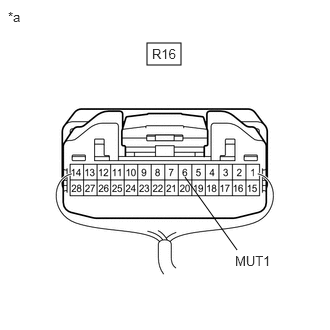
*a Component with harness connected
(Television Display Assembly)Standard Voltage
Tester Connection Condition Specified Condition R16-6 (MUT1) - Body ground Ignition switch ACC
RSE system playing
→ Changing source3.5 V or higher
→ Below 1 VResult
Proceed to OK NG
Result:
OK
PROCEED TO NEXT SUSPECTED AREA SHOWN IN PROBLEM SYMPTOMS TABLE. Refer to PROBLEM SYMPTOMS TABLE [12/2019 - 10/2022]
Result:
NG
See step 2
- Measure the voltage according to the value(s) in the table below.
- CHECK HARNESS AND CONNECTOR (RADIO AND DISPLAY RECEIVER ASSEMBLY - TELEVISION DISPLAY ASSEMBLY)
- Disconnect the H2 radio and display receiver assembly connector.
- Disconnect the R16 television display assembly connector.
- Measure the resistance according to the value(s) in the table below.
Standard Resistance
Tester Connection Condition Specified Condition R16-6 (MUT1) - H2-12 (MUTE) Always Below 1 Ω R16-6 (MUT1) or H2-12 (MUTE) - Body ground Always 10 kΩ or higher Result
Proceed to OK NG
Result:
NG
REPAIR OR REPLACE HARNESS OR CONNECTOR
Result:
OK
See step 3
- REPLACE TELEVISION DISPLAY ASSEMBLY
- Replace the television display assembly and check if it operates normally.
Refer to REMOVAL [12/2019 - 10/2022]
OK
The rear seat entertainment system operates normally.
Result
Proceed to OK NG
Result:
OK
END (TELEVISION DISPLAY ASSEMBLY WAS DEFECTIVE)
Result:
NG
PROCEED TO NEXT SUSPECTED AREA SHOWN IN PROBLEM SYMPTOMS TABLE. Refer to PROBLEM SYMPTOMS TABLE [12/2019 - 10/2022]
- Replace the television display assembly and check if it operates normally.