AVC-LAN Circuit [12/2019 - 10/2022]: Procedure
- CONFIRM MODEL
- Choose the model to be inspected.
Result
Result Proceed to For 8 Inch Display A For 12.3 Inch Display B
Result:
B
See step 5
Result:
A
See step 2
- Choose the model to be inspected.
- INSPECT RADIO AND DISPLAY RECEIVER ASSEMBLY
- Remove the radio and display receiver assembly.
Refer to REMOVAL [12/2019 - 10/2022]
- Measure the resistance according to the value(s) in the table below.
*a Component without harness connected
(Radio and Display Receiver Assembly)Standard Resistance
Tester Connection Condition Specified Condition H1-19 (TX+) - H1-20 (TX-) Always 60 to 80 Ω Result
Proceed to OK NG
Result:
NG
REPLACE RADIO AND DISPLAY RECEIVER ASSEMBLY. Refer to REMOVAL [12/2019 - 10/2022]
Result:
OK
See step 3
- Remove the radio and display receiver assembly.
- CHECK HARNESS AND CONNECTOR (AVC-LAN CIRCUIT)
- Disconnect the H1 radio and display receiver assembly connector.
- Disconnect the R16 television display assembly connector.
- Measure the resistance according to the value(s) in the table below.
Standard Resistance
Tester Connection Condition Specified Condition R16-4 (TX+) - H1-19 (TX+) Always Below 1 Ω R16-5 (TX-) - H1-20 (TX-) Always Below 1 Ω R16-4 (TX+) or H1-19 (TX+) - Body ground Always 10 kΩ or higher R16-5 (TX-) or H1-20 (TX-) - Body ground Always 10 kΩ or higher Result
Proceed to OK NG
Result:
NG
REPAIR OR REPLACE HARNESS OR CONNECTOR
Result:
OK
See step 4
- INSPECT MALFUNCTIONING PARTS
- Disconnect and reconnect each slave unit one by one until the master unit returns to normal operation.
HINT:
- Check all slave units.
- If disconnecting a slave unit causes the master unit to return to normal operation, the slave unit is defective and should be replaced.
OK
Master unit returns to normal operation.
Result
Proceed to OK NG
Result:
OK
REPLACE MALFUNCTIONING PARTS
Result:
NG
REPLACE RADIO AND DISPLAY RECEIVER ASSEMBLY. Refer to REMOVAL [12/2019 - 10/2022]
- Disconnect and reconnect each slave unit one by one until the master unit returns to normal operation.
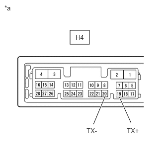
- INSPECT RADIO RECEIVER ASSEMBLY
- Remove the radio receiver assembly.
Refer to REMOVAL [12/2019 - 10/2022]
- Measure the resistance according to the value(s) in the table below.
*a Component without harness connected
(Radio Receiver Assembly)Standard Resistance
Tester Connection Condition Specified Condition H4-19 (TX+) - H4-20 (TX-) Always 60 to 80 Ω Result
Proceed to OK NG
Result:
NG
REPLACE RADIO RECEIVER ASSEMBLY. Refer to REMOVAL [12/2019 - 10/2022]
Result:
OK
See step 6
- Remove the radio receiver assembly.
- CHECK HARNESS AND CONNECTOR (AVC-LAN CIRCUIT)
- Disconnect the H4 radio receiver assembly connector.
- Disconnect the R16 television display assembly connector.
- Measure the resistance according to the value(s) in the table below.
Standard Resistance
Tester Connection Condition Specified Condition R16-4 (TX+) - H4-19 (TX+) Always Below 1 Ω R16-5 (TX-) - H4-20 (TX-) Always Below 1 Ω R16-4 (TX+) or H4-19 (TX+) - Body ground Always 10 kΩ or higher R16-5 (TX-) or H4-20 (TX-) - Body ground Always 10 kΩ or higher Result
Proceed to OK NG
Result:
NG
REPAIR OR REPLACE HARNESS OR CONNECTOR
Result:
OK
See step 7
- INSPECT MALFUNCTIONING PARTS
- Disconnect and reconnect each slave unit one by one until the master unit returns to normal operation.
HINT:
- Check all slave units.
- If disconnecting a slave unit causes the master unit to return to normal operation, the slave unit is defective and should be replaced.
OK
Master unit returns to normal operation.
Result
Proceed to OK NG
Result:
OK
REPLACE MALFUNCTIONING PARTS
Result:
NG
REPLACE RADIO RECEIVER ASSEMBLY. Refer to REMOVAL [12/2019 - 10/2022]
- Disconnect and reconnect each slave unit one by one until the master unit returns to normal operation.