The Camera Indicator is not Displayed [11/2023 - ]: Procedure
- CHECK HARNESS AND CONNECTOR (INNER REAR VIEW MIRROR ASSEMBLY - AUXILIARY BATTERY)
- Disconnect the inner rear view mirror assembly connector.
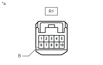
*a Front view of wire harness connector
(to Inner Rear View Mirror Assembly) - Measure the voltage according to the value(s) in the table below.
Standard Voltage
Tester Connection Switch Condition Specified Condition R1-6 (B) - Body ground Ignition switch off*1
Always*211 to 14 V - *1: for HV Model
- *2: for Gasoline Model
Result
Proceed to OK NG
Result:
NG
REPAIR OR REPLACE HARNESS OR CONNECTOR
Result:
OK
See step 2
- Disconnect the inner rear view mirror assembly connector.
- CHECK HARNESS AND CONNECTOR (INNER REAR VIEW MIRROR ASSEMBLY - IG POWER SUPPLY)
- Disconnect the inner rear view mirror assembly connector.
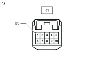
*a Front view of wire harness connector
(to Inner Rear View Mirror Assembly) - Measure the voltage according to the value(s) in the table below.
Standard Voltage
Tester Connection Switch Condition Specified Condition R1-1 (IG) - Body ground Ignition switch ON 11 to 14 V Result
Proceed to OK NG
Result:
NG
REPAIR OR REPLACE HARNESS OR CONNECTOR
Result:
OK
See step 3
- Disconnect the inner rear view mirror assembly connector.
- CHECK HARNESS AND CONNECTOR (INNER REAR VIEW MIRROR ASSEMBLY - BODY GROUND)
- Disconnect the inner rear view mirror assembly connector.
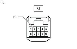
*a Front view of wire harness connector
(to Inner Rear View Mirror Assembly) - Measure the resistance according to the value(s) in the table below.
Standard Resistance
Tester Connection Condition Specified Condition R1-2 (E) - Body ground Always Below 1 Ω Result
Proceed to OK NG
Result:
OK
REPLACE INNER REAR VIEW MIRROR ASSEMBLY. Refer to REMOVAL [11/2023 - ]
Result:
NG
REPAIR OR REPLACE HARNESS OR CONNECTOR
- Disconnect the inner rear view mirror assembly connector.