Windshield Deicer does not Operate [12/2019 - 10/2022]: Procedure
- SYSTEM CHECK
- Check the vehicle specification.
Result
Result Proceed to For 8 Inch Display A For 12.3 Inch Display B
Result:
B
See step 5
Result:
A
See step 2
- Check the vehicle specification.
- CHECK AIR CONDITIONING SYSTEM
- Check that the air conditioning system.
HINT:
Both the windshield deicer system operation signal and air conditioning system operation signal are transmitted to the air conditioning amplifier assembly through the same communication line.
OK
The air conditioning system operates normally.
Result
Proceed to OK NG
Result:
NG
GO TO AIR CONDITIONING SYSTEM
For HV Model: Refer to HOW TO PROCEED WITH TROUBLESHOOTING [12/2019 - 10/2021] , or refer to HOW TO PROCEED WITH TROUBLESHOOTING [10/2021 - 11/2023]
For Gasoline Model with Automatic Air Conditioning System: Refer to HOW TO PROCEED WITH TROUBLESHOOTING [12/2019 - 10/2022]
For Gasoline Model with Manual Air Conditioning System: Refer to HOW TO PROCEED WITH TROUBLESHOOTING [12/2019 - 10/2022]
Result:
OK
See step 3
- Check that the air conditioning system.
- PERFORM ACTIVE TEST USING GTS
- Perform the Active Test according to the display on the GTS.
Body Electrical > Air Conditioner > Active Test
Tester Display Measurement Item Control Range Diagnostic Note Deicer Relay (Front) Windshield deicer wire (windshield glass) OFF or ON - Body Electrical > Air Conditioner > Active Test
Tester Display Deicer Relay (Front) OK
The windshield deicer system operates normally.
Result
Proceed to OK NG
Result:
NG
See step 9
Result:
OK
See step 4
- Perform the Active Test according to the display on the GTS.
- REPLACE AIR CONDITIONING AMPLIFIER ASSEMBLY
- Replace the air conditioning amplifier assembly with a new or known good one.
Refer to REMOVAL [12/2019 - 10/2022]
- Check that the windshield deicer system operates normally.
OK
The windshield deicer system operates normally.
Result
Proceed to OK NG
Result:
OK
END (AIR CONDITIONING AMPLIFIER ASSEMBLY WAS DEFECTIVE)
Result:
NG
REPLACE AIR CONDITIONING CONTROL ASSEMBLY
- Replace the air conditioning amplifier assembly with a new or known good one.
- CHECK HARNESS AND CONNECTOR (FRONT WIPER DEICER SWITCH - POWER SUPPLY)
- Disconnect the H37 front wiper deicer switch connector.
- Measure the voltage according to the value(s) in the table below.
Standard Voltage
Tester Connection Condition Specified Condition H37-5 (IG) - Body ground Ignition switch ON 11 to 14 V H37-5 (IG) - Body ground Ignition switch off Below 1 V Result
Proceed to OK NG
Result:
NG
REPAIR OR REPLACE HARNESS OR CONNECTOR
Result:
OK
See step 6
- CHECK HARNESS AND CONNECTOR (FRONT WIPER DEICER SWITCH - BODY GROUND)
- Measure the resistance according to the value(s) in the table below.
Standard Resistance
Tester Connection Condition Specified Condition H37-2 (E) - Body ground Always Below 1 Ω Result
Proceed to OK NG
Result:
NG
REPAIR OR REPLACE HARNESS OR CONNECTOR
Result:
OK
See step 7
- Measure the resistance according to the value(s) in the table below.
- CHECK HARNESS AND CONNECTOR (FRONT WIPER DEICER SWITCH - DEICER RELAY)
- Remove the DEICER relay from the No. 1 engine room relay block and No. 1 junction block assembly.
- Measure the resistance according to the value(s) in the table below.
Standard Resistance
Tester Connection Condition Specified Condition DEICER relay holder terminal 1 - H37-4 (D) Always Below 1 Ω Result
Proceed to OK NG
Result:
NG
REPAIR OR REPLACE HARNESS OR CONNECTOR
Result:
OK
See step 8
- INSPECT FRONT WIPER DEICER SWITCH
Refer to ON-VEHICLE INSPECTION [12/2019 - ]
Result
Proceed to OK NG Result:
NG
REPLACE FRONT WIPER DEICER SWITCH. Refer to REMOVAL [12/2019 - ]
Result:
OK
See step 9
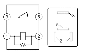
- INSPECT DEICER RELAY
- Measure the resistance according to the value(s) in the table below.
Standard Resistance
Tester Connection Condition Specified Condition 3 - 5 Auxiliary battery voltage applied between terminals 1 and 2 Below 1 Ω 3 - 5 Auxiliary battery voltage not applied between terminals 10 kΩ or higher Result
Proceed to OK NG
Result:
NG
REPLACE DEICER RELAY
Result:
OK
See step 10
- Measure the resistance according to the value(s) in the table below.
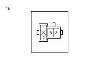
- CHECK WIRE HARNESS AND CONNECTOR (DEICER RELAY - POWER SUPPLY)
- Measure the voltage according to the value(s) in the table below.
*a DEICER Relay Holder Standard Voltage
Tester Connection Condition Specified Condition DEICER relay holder terminal 2 - Body ground Ignition switch ON 11 to 14 V DEICER relay holder terminal 3 - Body ground Ignition switch off*1
Always*211 to 14 V - *1: for HV Model
- *2: for Gasoline Model
Result
Proceed to OK NG
Result:
NG
REPAIR OR REPLACE HARNESS OR CONNECTOR
Result:
OK
See step 11
- Measure the voltage according to the value(s) in the table below.
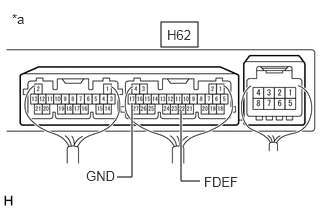
- CHECK WIRE HARNESS AND CONNECTOR (DEICER RELAY - AIR CONDITIONING AMPLIFIER ASSEMBLY)
- Disconnect the H62 air conditioning amplifier assembly connector.
*a DEICER Relay Holder - Measure the resistance according to the value(s) in the table below.
Standard Resistance
Tester Connection Condition Specified Condition DEICER relay holder terminal 1 - H62-22 (FDEF) Always Below 1 Ω DEICER relay holder terminal 1 or H62-22 (FDEF) - Body ground Always 10 kΩ higher Result
Proceed to OK NG
Result:
NG
REPAIR OR REPLACE HARNESS OR CONNECTOR
Result:
OK
See step 12
- Disconnect the H62 air conditioning amplifier assembly connector.
- CHECK AIR CONDITIONING AMPLIFIER ASSEMBLY
- Connect the H62 air conditioning amplifier assembly connector.
- Measure the voltage according to the value(s) in the table below.
*a Component with harness connected
(Air Conditioning Amplifier Assembly)Standard Voltage
Tester Connection Condition Specified Condition H62-22 (FDEF) - H62-17 (GND) Ignition switch ON, Front wiper deicer switch on Below 1 V H62-22 (FDEF) - H62-17 (GND) Ignition switch ON, Front wiper deicer switch off 11 to 14 V Result
Proceed to OK NG
Result:
NG
REPLACE AIR CONDITIONING AMPLIFIER ASSEMBLY
Result:
OK
See step 13
- CHECK WIRE HARNESS AND CONNECTOR (DEICER RELAY - WINDSHIELD DEICER WIRE (WINDSHIELD GLASS))
- Disconnect A60 windshield deicer wire (windshield glass) connector.
*a DEICER Relay Holder - Measure the resistance according to the value(s) in the table below.
Standard Resistance
Tester Connection Condition Specified Condition DEICER relay holder terminal 5 - A60-1 (B) Always Below 1 Ω DEICER relay holder terminal 5 - A60-3 (B2) Always Below 1 Ω A60-1 (B) - Body ground Always 10 kΩ higher A60-3 (B2) - Body ground Always 10 kΩ higher DEICER relay holder terminal 5 - Body ground Always 10 kΩ higher Result
Proceed to OK NG
Result:
NG
REPAIR OR REPLACE HARNESS OR CONNECTOR
Result:
OK
See step 14
- Disconnect A60 windshield deicer wire (windshield glass) connector.
- CHECK WIRE HARNESS AND CONNECTOR (WINDSHIELD DEICER WIRE (WINDSHIELD GLASS) - BODY GROUND)
- Measure the resistance according to the value(s) in the table below.
Standard Resistance
Tester Connection Condition Specified Condition A60-2 (E) - Body ground Always Below 1 Ω Result
Proceed to OK NG
Result:
OK
REPLACE WINDSHIELD DEICER WIRE (WINDSHIELD GLASS). Refer to REMOVAL [12/2019 - 09/2020] , or refer to REMOVAL [09/2020 - 10/2021] , or refer to REMOVAL [10/2021 - 11/2023]
Result:
NG
REPAIR OR REPLACE HARNESS OR CONNECTOR
- Measure the resistance according to the value(s) in the table below.