2021 Highlander, Highlander HV Pre-Delivery Service (PDS) (T-SB-0087-20)
Reference number: T-SB-0087-20
2021 HIGHLANDER, HIGHLANDER HV PRE-DELIVERY SERVICE (PDS)
TECHNICAL SERVICE BULLETIN
| TOYOTA: | 2021 Highlander, Highlander HV |
| SERVICE CATEGORY: | General |
| SECTION: | Pre-Delivery Service |
| MARKET: | USA |
| COPYRIGHT: | © 2018 Toyota, USA License Agreement TMS1002 |
APPLICABILITY
| YEAR(S) | MODEL(S) | ADDITIONAL INFORMATION |
|---|---|---|
| 2021 | Highlander, Highlander HV |
INTRODUCTION
Pre-Delivery Service (PDS) is a critical step in satisfying our new car customers. Customer feedback indicates the following areas deserve special attention when performing PDS:
- Careful inspection for paint chips/scratches and body dents/dings.
- Proper operation of electrical accessories (including interior light, clock, and radio reset).
- Interior cleanliness.
- Proper function of mechanical systems.
Customer retention and proper maintenance of vehicles are and have always been a major focus for Toyota. To help remind customers that regular service is essential to the proper maintenance of the vehicle, dealers are required to install a service reminder sticker before delivery. By doing this, customers will be reminded to return to your dealership for service. Your current service reminder sticker may be used. (See PDS Check Sheet item 8 of "Final Inspection and Cleaning.")
This bulletin contains the PDS procedures which apply specifically to 2021 model year Highlander and Highlander Hybrid vehicles. A universal PDS Check Sheet that contains PDS steps that apply to all 2021 model year Toyota vehicles has been developed. To properly perform a complete PDS, you must complete all procedures contained in this TSB as well as the universal PDS Check Sheet .
In addition, if the vehicle is stored for over 30 days, be sure to follow Long-Term Vehicle Storage Guidelines .
WARRANTY POLICY
If the need for additional repairs or adjustment is noted during PDS, the required service should be performed under warranty. Reimbursement will be managed under the warranty policy.
The Warranty Policy and Procedures Manual requires that you maintain the completed Check Sheet in the customer's file . If you cannot produce a completed form for each retailed vehicle upon TMS and/or Region/Distributor audit, the PDS payment amount will be subject to debit.
An additional Repair Order completed in conjunction with normal PDS MUST have time punch/flags for service. If multiple repairs are performed, separate time flags MUST be punched for each repair.
WARRANTY INFORMATION
| OP CODE | DESCRIPTION | MODEL | TIME | OFP | T1 | T2 |
|---|---|---|---|---|---|---|
| 001013 | Pre-Delivery Service (PDS) | Highlander | 1.0 | - | - | - |
| Highlander HV | 1.4 |
REQUIRED TOOLS & EQUIPMENT
| REQUIRED EQUIPMENT | SUPPLIER | PART NUMBER | QTY | ||
|---|---|---|---|---|---|
| Techstream ADVi(1) | ADE | TSADVUNIT | 1 | ||
| Techstream 2.0 | TS2UNIT | ||||
| Techstream Lite | TSLITEPDLR01 | ||||
| Techstream Lite (Green Cable) | TSLP2DLR01 | ||||
|
|||||
- Only ONE of the Techstream units listed above is required.
- Software version 15.00.028 or later is required.
- Additional Techstream units may be ordered by calling Approved Dealer Equipment (ADE) at 1-800-368-6787.
PROCEDURES
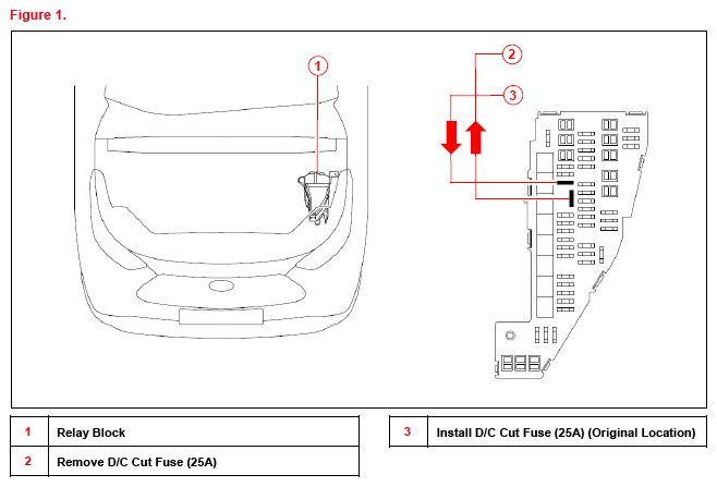
D/C CUT FUSE INSTALLATION
To minimize battery discharge, the D/C cut fuse (25A) has been removed and is stored in the engine compartment relay block. Install the D/C cut fuse (25A) and confirm ALL related Diagnostic Trouble Codes (DTCs) are cleared.
SEATING POSITION CONTROL ECU INITIALIZATION
Refer to the applicable Repair Manual for the seating position control ECU initialization procedure (procedure 2).
MEMORIZE STEERING ANGLE NEUTRAL POINT
As a result of the removal of the D/C cut fuse, the power source to the steering angle sensor is cut off. When the D/C cut fuse is reinstalled, the parking assist monitor system/panoramic view monitor system will be operative, but it cannot display guidelines to assist parking operation because the center position recognized by the steering angle sensor may not be in an initial position. Therefore, perform steering angle neutral point initialization AFTER installing the D/C cut fuse during PDS.
Refer to the applicable Repair Manual for the steering angle neutral point initialization procedure .
PERFORM STEERING SENSOR ZERO POINT CALIBRATION
As a result of the removal of the D/C cut fuse, the steering angle sensor power source is cut off.
When the D/C cut fuse is reinstalled, the center position recognized by the steering angle sensor may not be the appropriate position. Therefore, it is necessary to perform steering sensor zero point calibration AFTER installing the D/C cut fuse during PDS.
Refer to the applicable Repair Manual for the steering zero point calibration procedure:
- Driving Method.
- Techstream Method (procedure 4).
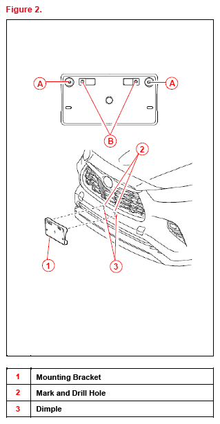
FRONT LICENSE PLATE AND MOUNTING BRACKET INSTALLATION
The front license plate bracket and two self-tapping screws are stored in the vehicle. Follow this procedure to install the front license plate bracket and front license plate in states where it is required by law.
- Align holes "A" of the mounting bracket with the dimples on the radiator lower grille. Mark the location of holes "B" on the radiator lower grille.NOTE:
- Holes "A" are used for installation of the mounting bracket to the radiator lower grille.
- Holes "B" are used for the installation of the front license plate to the mounting bracket.
- Drill two relief holes with a diameter of 11 mm (0.43 in.) at the hole "B" marks on the front bumper cover to prevent the license plate retaining bolt end from contacting the radiator lower grille.NOTE:
- Do NOT drill holes in the dimples.
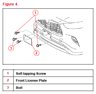
- Do NOT overtighten the self-tapping screws.
- Install the mounting bracket to the radiator lower grille using two self-tapping screws.
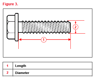
- Install the front license plate onto the mounting bracket at holes "B" using two noncorroding bolts with the following dimensions:
Length: 15.0 mm (0.59 in.)
Diameter: 6.0 mm (0.24 in.)
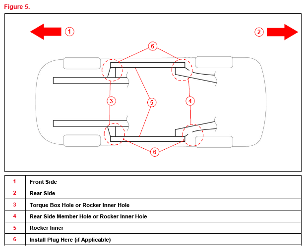
INSTALLATION OF RUBBER BODY PLUGS
- Confirm the number of plugs in the glove box. If two plugs are present, perform substep 2A ONLY. If four plugs are present, perform substep 2A AND substep 2B.
- Install plugs according the instructions below by confirming the number of plugs in the glove box.
- Install two plugs in the rear side member hole or rocker inner hole (see Figure 5).
- Install two plugs in the torque box hole or rocker inner hole (see Figure 5).
NOTE:- The installation of these plugs is required to prevent rust.
- These plugs are stored in the glove box.
- The number of plugs may vary according to production locations in the same vehicle model.
TIRE PRESSURE WARNING SYSTEM (TPWS) INITIALIZATION
Refer to the applicable Repair Manual for the TPWS initialization procedure .
DEALER CONTACT INFORMATION FOR CALL DEALER HEAD UNIT FUNCTION
Refer to the Multimedia System Owner's Manual to add dealer contact information .
ENTUNE™ 3.0 APP SUITE CONNECT INITIALIZATION/UPDATE
Refer to T-SB-0039-20 Entune™ 3.0 App Suite Connect to initialize/update the Entune™ 3.0 App Suite Connect.