Air Conditioning Leak Detection Dye And O-Ring Joint Inspections (T-SB-0058-23 REV1)
WARNING: This page is about the Highlander Hybrid LE, 2.5L Eng VIN A, which is a different variant/trim than selected.
Publication date: 2025-06-13Reference number: T-SB-0058-23 REV1
Supersedes refnos: T-SB-0058-23
AIR CONDITIONING LEAK DETECTION DYE AND O-RING JOINT INSPECTIONS
TECHNICAL SERVICE BULLETIN
Reference Number(s): T-SB-0058-23 Rev1, Date of Issue:
June 13, 2025
Superceded Bulletin(s): T-SB-0058-23, Date of Issue:
August 21, 2023
| TOYOTA: | 2025 4Runner HV, Crown Signia, Prius PHV, RAV4 PHV; 2013 - 2025 4Runner, Avanza, Camry, Camry HV, Corolla, Hiace, Highlander, Highlander HV, Prius, RAV4, Tundra; 2017 - 2020, 2022 - 2025 86; 2013 - 2022 Avalon, Avalon HV, Sequoia; 2022 - 2025 Corolla Cross, Tundra HV; 2019 - 2025 Corolla Hatchback; 2023 - 2026 Crown; 2013 - 2021 FJ Cruiser, Matrix, Prius C; 2024 - 2025 Grand Highlander, Grand Highlander HV, Tacoma, Tacoma HV; 2013 - 2021, 2024 - 2025 Land Cruiser; 2018 Mirai (Canada); 2016 - 2025 Mirai, RAV4 HV; 2013 - 2015 Prius PHV; 2017 - 2024 Prius Prime; 2013 - 2018 Prius V; 2021 - 2024 RAV4 Prime; 2022 - 2024 Raize; 2022 - 2025 Sienna HV MaaS Package; 2021 - 2025 Sienna HV; 2013 - 2020 Sienna; 2021 - 2024 Venza HV; 2013 - 2016 Venza; 2020 Yaris HB MEX-Prod; 2016 - 2020 Yaris R, Yaris SD MEX-Prod; 2017 - 2025 Yaris THAI-Prod; 2013 - 2019, 2022 - 2023, 2025 - 2026 Yaris; 2023 - 2025 bZ4X, GR Corolla, Yaris SD THAI-Prod; 2017 - 2018 iA, iM |
| SERVICE CATEGORY: | Vehicle Interior |
| SECTION: | Heating/Air Conditioning |
| MARKET: | USA and Mexico |
| COPYRIGHT: | © 2018 Toyota, USA License Agreement TMS1002 |
APPLICABILITY
APPLICABILITY
| YEAR(S) | MODEL(S) | ADDITIONAL INFORMATION |
|---|---|---|
| 2025 | 4Runner HV, Crown Signia, Prius PHV, RAV4 PHV | |
| 2013 - 2025 | 4Runner, Avanza, Camry, Camry HV, Corolla, Hiace, Highlander, Highlander HV, Prius, RAV4, Tundra | |
| 2017 - 2020, 2022 - 2025 | 86 | |
| 2013 - 2022 | Avalon, Avalon HV, Sequoia | |
| 2022 - 2025 | Corolla Cross, Tundra HV | |
| 2019 - 2025 | Corolla Hatchback | |
| 2023 - 2026 | Crown | |
| 2013 - 2021 | FJ Cruiser, Matrix, Prius C | |
| 2024 - 2025 | Grand Highlander, Grand Highlander HV, Tacoma, Tacoma HV | |
| 2013 - 2021, 2024 - 2025 | Land Cruiser | |
| 2018 | Mirai (Canada) | |
| 2016 - 2025 | Mirai, RAV4 HV | |
| 2013 - 2015 | Prius PHV | |
| 2017 - 2024 | Prius Prime | |
| 2013 - 2018 | Prius V | |
| 2021 - 2024 | RAV4 Prime | |
| 2022 - 2024 | Raize | |
| 2022 - 2025 | Sienna HV MaaS Package | |
| 2021 - 2025 | Sienna HV | |
| 2013 - 2020 | Sienna | |
| 2021 - 2024 | Venza HV | |
| 2013 - 2016 | Venza | |
| 2020 | Yaris HB MEX-Prod | |
| 2016 - 2020 | Yaris R, Yaris SD MEX-Prod | |
| 2017 - 2025 | Yaris THAI-Prod | |
| 2013 - 2019, 2022 - 2023, 2025 - 2026 | Yaris | |
| 2023 - 2025 | bZ4X, GR Corolla, Yaris SD THAI-Prod | |
| 2017 - 2018 | iA, iM |
REVISION NOTICE
June 13, 2025 Rev1:
- Applicability has been updated to include 2017 - 2019 and 2024 model year Prius Prime, 2020 model year Sienna, 2021 and 2024 - 2025 model year Sienna HV, 2024 - 2026 model year Crown, and Yaris, 2024 model year Raize, and Venza HV, 2024 - 2025 model year 86, 4Runner, Avanza, bZ4X, Camry, Camry HV, Corolla, Corolla Cross, Corolla Hatchback, GR Corolla, Grand Highlander, Grand Highlander HV, Hiace, Highlander, Highlander HV, Land Cruiser, Mirai, Prius, RAV4, RAV4 HV, Sienna HV MaaS Package, Tacoma, Tacoma HV, Tundra, Tundra HV, Yaris SD THAI-Prod, Yaris THAI-Prod, 2025 model year 4Runner HV, Crown Signia, Prius PHV, and RAV4 PHV vehicles.
- The Introduction, Parts Information, Required Tools & Equipment, and Air Conditioning Leak Detection Dye and Injection Tool Use sections have been updated.
Any previous printed versions of this bulletin should be discarded.
INTRODUCTION
The air conditioning dye injection tool kit has been developed to aid in identifying the location of air conditioning refrigerant leaks. Follow the procedures outlined in this Service Bulletin to aid in locating, inspecting, and repairing refrigerant leaks.
WARRANTY INFORMATION
FOR USA MARKET
WARRANTY INFORMATION
| OP CODE | DESCRIPTION | TIME | OFP | T1 | T2 |
|---|---|---|---|---|---|
| N/A | Not Applicable to Warranty | - | - | - | - |
FOR MEXICO MARKET
WARRANTY INFORMATION
| OP CODE | DESCRIPTION | TIME | OFP | T1 | T2 |
|---|---|---|---|---|---|
| N/A | Not Applicable to Warranty | - | - | - | - |
PARTS INFORMATION
FOR USA AND MEXICO MARKETS
PARTS INFORMATION
| PART NUMBER | PART NAME | QTY | ||
|---|---|---|---|---|
| 00289-DYE11(1) | ND-11 A/C Dye Cartridges | 1 | ||
| 00289-DYE12(1) | ND-12 A/C Dye Cartridges | 1 | ||
|
||||
NOTE:
- A/C dye cartridges are available through ZEP Products. The dye can be ordered through the TCMC (Toyota Complete Maintenance Care) Program website via Dealer Daily.
- Each part number contains two dye cartridges.
REQUIRED TOOLS & EQUIPMENT
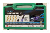
The table below shows a list of the components included in the air conditioning dye injection tool kit if ANY of the components requires replacement.
TABLE 1
| SPECIAL SERVICE TOOL (SST) | ||||||
|---|---|---|---|---|---|---|
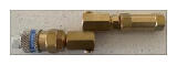
| TOOL KIT | DYE TYPE | REFRIGERANT TYPE/DESCRIPTION | SUB-PART NUMBERS | IMAGE | ||
| 09870-DYEKIT(1) | ND-11 (00289-DYE11) | R-134a/Brass Coupler(1) | 09870-10010-Y | |||
| R-1234yf/Brass Coupler(1) | 09870-20010-Y | |||||
| ND-12 (00289-DYE12) | R-134a/Brass Coupler(1) | 09870-10010-B | ||||
| R-1234yf/Brass Coupler(1) | 09870-20010-B | |||||
| - | Injector Handle(1) | 09870-TP9845 | ||||
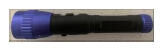
| - | Ultraviolet (UV) Flashlight(1) | 09870-TPOPUVP | ||||
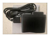
| - | Flashlight Charger(1) | 09870-0TP14 | ||||
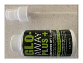
| - | GLO-AWAY + Dye Cleaner(1) | 09870-0TP19 | ||||
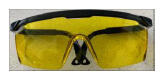
| - | Yellow Glasses(1) | 09870-TP9940 | ||||
| - | Case(1) | 09870-CASE | ||||
|
||||||

NOTE:
Replacement components may be ordered by calling Approved Dealer Equipment (ADE) at 1-800-368-6787 (USA) or 01-55-50103041 (Mexico).
PARTS INFORMATION
| REQUIRED TOOLS & MATERIAL | QTY |
|---|---|
| R1234YF A/C Machine | 1 |
| R134A A/C Machine | 1 |
AIR CONDITIONING LEAK DETECTION DYE AND INJECTION TOOL USE
CAUTION:
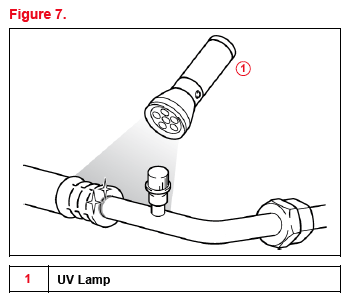
- Do NOT look directly into the UV flashlight and ALWAYS wear UV protection glasses.
- Wear safety glasses when connecting/disconnecting the dye injection tool from the air conditioning service port.
- Do NOT operate the air conditioning system while the dye injection tool is connected to air conditioning system.
- Do NOT connect the dye injection tool to a system that is evacuated.
- The air conditioning system MUST contain enough refrigerant to operate the compressor and circulate the dye to find leaks.
- Do NOT mix ND-11 and ND-12 dyes. ALWAYS use the dye cartridge with the designated injector tool brass coupler.
- After use, store the injector tool and dye cartridges in a cool place, away from sunlight.
- Dispose of ANY dye in accordance with all local, state, and federal regulations.
NOTE:
Two dye cartridges are required per vehicle service. The first cartridge will be completely purged through the brass coupler to ensure there are NO contaminants such as moisture, air, etc. The second cartridge will be injected into the air conditioning system to inspect for leaks.
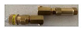
- The air conditioning dye injection tool kit includes four brass couplers to accommodate vehicles for the types of compressor oils and refrigerants, refer to the Required Tools & Equipment
section for details:
- ND-11 with R-134a compressor oil; electric compressors (09870-10010-Y)
- ND-11 with R-1234yf compressor oil; electric compressors (09870-20010-Y)
- ND-12 with R-134a compressor oil; belt driven compressors (09870-10010-B)
- ND-12 with R-1234yf compressor oil; belt driven compressors (09870-20010-B)
NOTE:- ND-12 compressor oil is compatible with ND-8 oil systems.
- ND-8 compressor oil is NOT compatible with ND-12 oil systems.
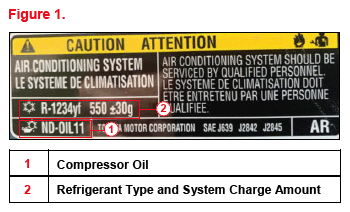
- Identify the compressor oil and refrigerant system type by looking at the under-hood air conditioning label for the compressor oil and refrigerant type the vehicle is using and select the corresponding dye injector tool brass coupler.
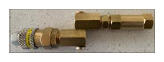
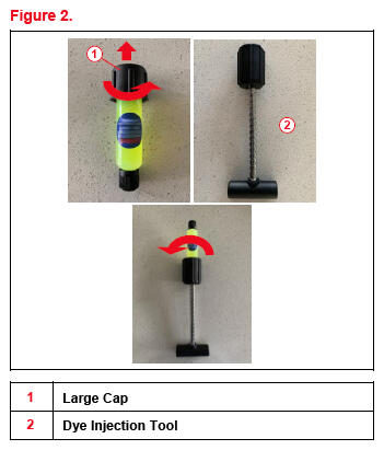
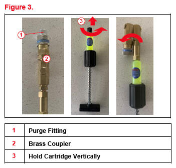
- Prepare the dye injection tool with the dye cartridge by removing the large cap from the first cartridge.
- Completely unscrew the handle on the injector and screw the dye cartridge into it.NOTE: When screwing on the dye cartridge to the injector handle, make sure the piston rod remains in the fully unscrewed position.
- Remove the purge fitting from the brass coupler and hold the cartridge vertically with the small cap on top.
- Remove the cap and screw the cartridge firmly to the brass coupler.
- Insert the purge fitting into the brass coupler.
- AFTER the purge fitting is installed, continue holding the dye injection tool in the vertical position to avoid dye form leaking out until the purge process is complete.
- Turn the handle to advance the plunger until it stops, passing all the dye out of the cartridge.
- Remove the purge fitting from the brass coupler.
- Completely unscrew the handle on the injector and unscrew the first empty cartridge from the brass coupler and dispose.
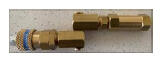
- Install the second cartridge onto the brass coupler.
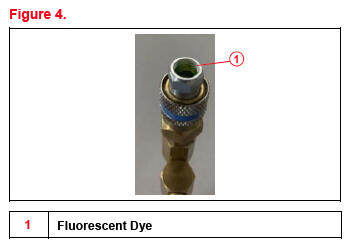
- Install the purge fitting to the brass coupler and turn the handle to advance the plunger until a small amount of fluorescent dye exits the purge fitting.
- Remove the purge fitting. The injection tool assembly is now purged and ready for use.
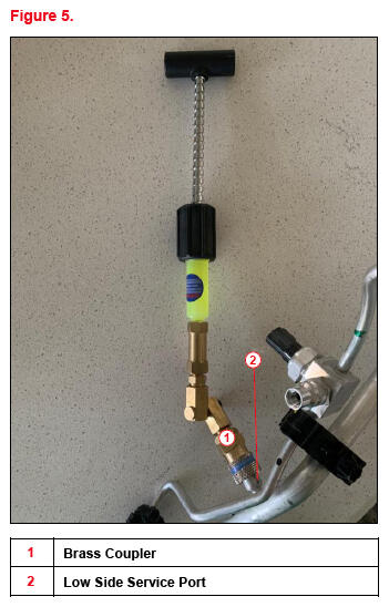
- Connect the brass coupler to the low side service port.NOTE: Wrap the coupler connection with a shop rag as a small amount of dye may spray out due to refrigerant pressure.
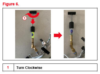
- Turn the plunger clockwise to inject all the dye into the vehicle.
- Disconnect the brass coupler from the service port and wipe both clean.NOTE: Wrap the coupler connection with a shop rag as a small amount of dye may spray out due to refrigerant pressure.
- Start the engine, turn the air conditioning switch ON, set the temperature to MAX COOL, and run the compressor for 10 minutes to circulate the dye through the system.
- Turn OFF the air conditioning and engine. Put on UV glasses and check for refrigerant leaks along the air conditioning system components while shining the UV light.
HINT
- Areas where there are refrigerant leaks will glow in a bright yellow green.
- For smaller leaks, operate the air conditioning system over the next 24 to 48 hours and reinspect periodically.
- AFTER the leaks are repaired, use the GLO-AWAY, dye cleaner, and UV flashlight to clean the area and ensure NO dye remains.
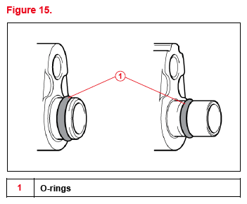
HVAC O-RING JOINT INSPECTIONS
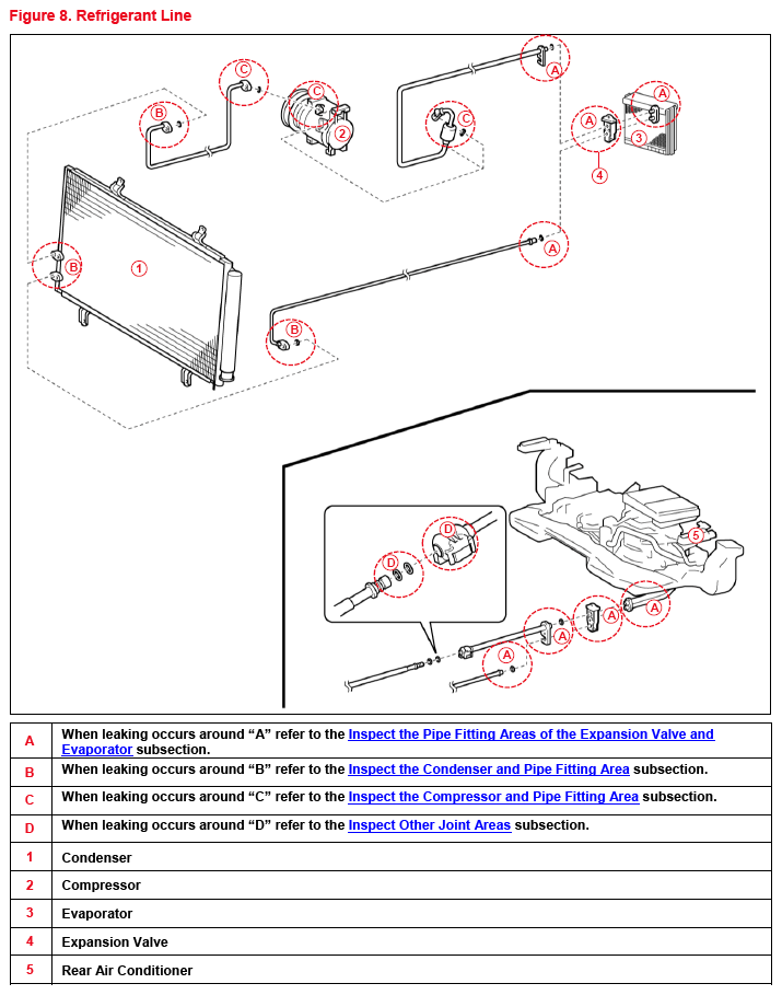
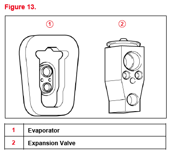
INSPECT THE PIPE FITTING AREAS OF THE EXPANSION VALVE AND EVAPORATOR
NOTE:
- Do NOT reuse the O-rings once they are removed.
- As there may be a malfunction in multiple components, make sure to complete ALL steps and replace ALL parts in which defects are found.
- If no malfunction is found in ANY related parts, a temporary leak may have occurred due to foreign matter on an O-ring, deformation, etc.
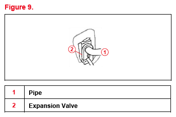
- Remove the pipes from the expansion valve.NOTE:
- Wipe off the joint area with a clean cloth BEFORE disassembly.
- Slowly remove the pipes straight to prevent the sealing face from being damaged and foreign materials from dropping off.
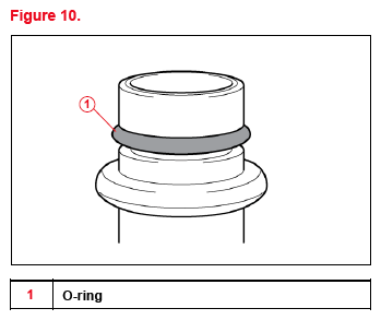
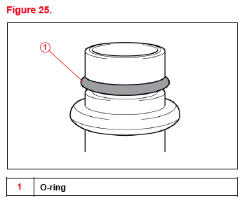
- Inspect the ENTIRE O-ring surfaces making sure they are free from defects, such as damage (cuts, dents, or crushed areas), foreign material adhesion, or twists. If there are ANY defects, clean or replace the part. Refer to the O-ring Abnormalities
subsection for judgement criteria.NOTE:
- Inspect the O-ring surfaces in a well-lit area.
- When it is difficult to inspect the surface conditions due to oil adhesion, degrease the surface (such as by wiping it with a clean white cloth). Make sure NOT to lose any foreign material that was adhering to the surface that may indicate the source of the leak.
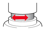
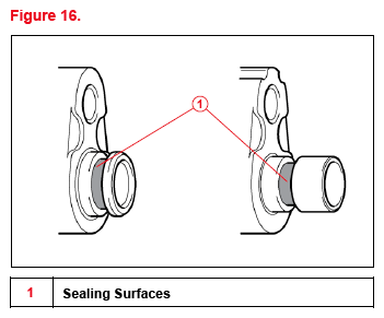
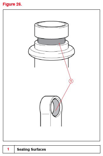
- Remove the O-rings and inspect the entire pipe surfaces making sure they are free from defects, such as foreign material adhesion, damage, or corrosion. If there are ANY defects, clean or replace the part. Refer to the Sealing Surface Abnormalities (O-ring Attachment Area)
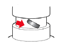
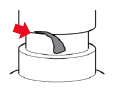
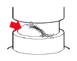
subsection for judgment criteria.NOTE: When removing the O-rings, use soft tools (such as a toothpick) to avoid damaging the sealing face or the O-ring.
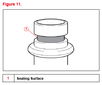
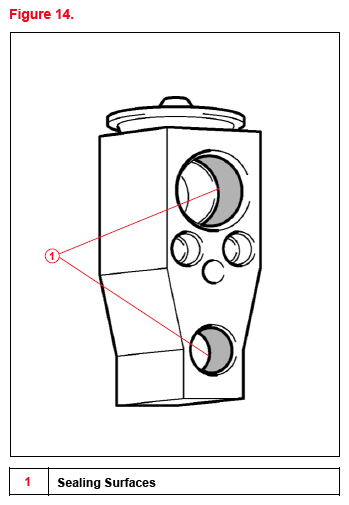
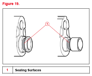
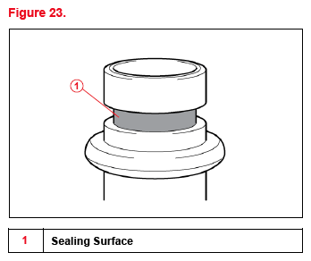
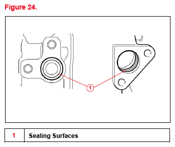
- Inspect the ENTIRE sealing surfaces of the expansion valve (pipe side) making sure they are free from defects, such as foreign material adhesion, damage, or corrosion. If there are ANY defects, clean or replace the part. Refer to the Sealing Surface Abnormalities (Part Joint Area)
subsection for judgment criteria.NOTE: When it is difficult to check the surface conditions due to oil adhesion, degrease the surface (such as by wiping it with a clean white cloth). Make sure NOT to lose any foreign material that was adhering to the surface that may indicate the source of the leak.
- Remove the expansion valve from the evaporator.NOTE:
- Slowly remove the pipes straight to prevent the sealing face from being damaged and foreign materials from dropping off.
- If the expansion valve is difficult to remove, gently move it up and down and right to left for removal.
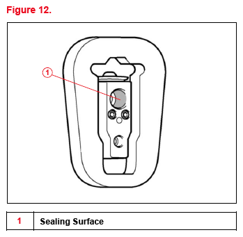
- Inspect the ENTIRE sealing surfaces of the expansion valve (evaporator side) making sure they are free from defects, such as foreign material adhesion, damage, or corrosion. If there are ANY defects, clean or replace the part. Refer to the Sealing Surface Abnormalities (Part Joint Area)
subsection for judgment criteria.NOTE: When it is difficult to inspect the surface conditions due to oil adhesion, degrease the surface (such as by wiping it with a clean white cloth). Make sure NOT to lose any foreign material that was adhering to the surface that may indicate the source of the leak.
- Inspect the ENTIRE O-ring surfaces of the evaporator making sure they are free from defects, such as damage (cuts, dents, or crushed areas), foreign material adhesion, or twists. If there are ANY defects, clean or replace the part. Refer to the O-ring Abnormalities
subsection for judgement criteria.NOTE:
- Inspect the O-ring surfaces in a well-lit area.
- When it is difficult to inspect the surface conditions due to oil adhesion, degrease the surface (such as by wiping it with a clean white cloth). Make sure NOT to lose any foreign material that was adhering to the surface that may indicate the source of the leak.
- Inspect the ENTIRE evaporator surface by remove the O-rings making sure they are free from defects, such as foreign material adhesion, damage, or corrosion. If there are ANY defects, clean or replace the part. Refer to the Sealing Surface Abnormalities (O-ring Attachment Area)
subsection for judgment criteria.NOTE: When removing the O-rings, use soft tools (such as a toothpick) to avoid damaging the sealing face or the O-ring.
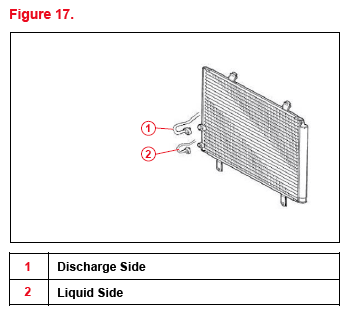
INSPECT THE CONDENSER AND PIPE FITTING AREA
NOTE:
- Do NOT reuse the O-rings once they are removed.
- As there may be a malfunction in multiple components, make sure to complete ALL steps and replace ALL the parts in which defects are found.
- If no malfunction is found in ANY related parts, a temporary leak may have occurred due to foreign matter on an O-ring, deformation, etc.
- Remove the discharge and liquid pipes from the condenser.NOTE:
- Wipe off the joint area with a clean cloth before disassembly.
- Slowly remove the pipes straight to prevent the sealing face from being damaged and foreign materials from dropping off.
- Inspect the ENTIRE O-ring surfaces making sure they are free from defects, such as damage (cuts, dents, or crushed areas), foreign material adhesion, or twists. If there are ANY defects, clean or replace the part. Refer to the O-ring Abnormalities
subsection for judgement criteria.NOTE:
- Inspect the O-ring surfaces in a well-lit area.
- When it is difficult to inspect the surface conditions due to oil adhesion, degrease the surface (such as by wiping it with a clean white cloth). Make sure NOT to lose any foreign material that was adhering to the surface that may indicate the source of the leak.
- Inspect the ENTIRE pipe surfaces by removing the O-rings making sure they are free from defects, such as foreign material adhesion, damage, or corrosion. If there are ANY defects, clean or replace the part. Refer to the Sealing Surface Abnormalities (O-ring Attachment Area)
subsection for judgment criteria.NOTE: When removing the O-rings, use soft tools (such as a toothpick) to avoid damaging the sealing face or the O-ring.
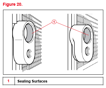
- Inspect the ENTIRE sealing surface of the condenser making sure it is free from defects, such as foreign material adhesion, damage, or corrosion. If there are ANY defects, clean or replace the part. Refer to the Sealing Surface Abnormalities (Part Joint Area)
subsection for judgment criteria.NOTE: When removing the O-rings, use soft tools (such as a toothpick) to avoid damaging the sealing face or the O-ring.
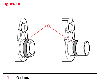
INSPECT THE COMPRESSOR AND PIPE FITTING AREA
NOTE:
- Do NOT reuse the O-rings once they are removed.
- As there may be a malfunction in multiple components, make sure to complete ALL and replace ALL the parts in which defects are found.
- If no malfunction is found in ANY related parts, a temporary leak may have occurred due to foreign matter on an O-ring, deformation, etc.
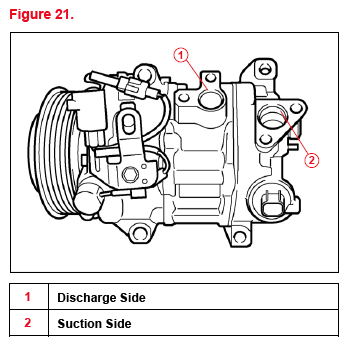
- Remove the discharge and suction pipes from the compressor.NOTE:
- Wipe off the joint area with a clean cloth before disassembly.
- Slowly remove the pipes straight to prevent the sealing face from being damaged and foreign materials from dropping off.
- Inspect the ENTIRE O-ring surfaces, making sure they are free from defects, such as damage (cuts, dents, or crushed areas), foreign material adhesion or twists. If there are ANY defects, clean or replace the part. Refer to the O-ring Abnormalities
subsection for judgement criteria.NOTE:
- Inspect the O-ring surfaces in a well-lit area.
- When it is difficult to inspect the surface conditions due to oil adhesion, degrease the surface (such as by wiping it with a clean white cloth). Make sure not to lose any foreign material that was adhering to the surface that may indicate the source of the leak.
- Inspect the entire pipe surfaces by removing the O-rings making sure they are free from defects, such as foreign material adhesion, damage, or corrosion. If there are ANY defects, clean or replace the part. Refer to the Sealing Surface Abnormalities (O-ring Attachment Area)
subsection for judgement criteria.NOTE: When removing the O-rings, use soft tools (such as a toothpick) to avoid damaging the sealing face or the O-ring.
- Inspect the ENTIRE sealing surface of the compressor making sure it is free from defects, such as foreign material adhesion, damage, or corrosion. If there are ANY defects, clean or replace the part. Refer to the Sealing Surface Abnormalities (Part Joint Area)
subsection for judgment criteria.NOTE: When it is difficult to inspect the surface conditions due to oil adhesion, degrease the surface (such as by wiping it with a clean white cloth). Make sure NOT to lose any foreign material that was adhering to the surface that may indicate the source of the leak.
INSPECT OTHER JOINT AREAS
NOTE:
- Do NOT reuse the O-rings once they are removed.
- Make sure to inspect all the related parts and replace all the parts where defects are found.
- If no malfunction is found in ANY related parts, a temporary leak may have occurred due to foreign matter on an O-ring, deformation, etc.
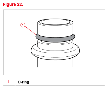
- Inspect the ENTIRE O-ring surface of the pipe or part making sure they are free from defects, such as damage (cuts, dents, or crushed areas), foreign material adhesion or twists. If there are ANY defects, clean or replace the part. Refer to the O-ring Abnormalities
subsection for judgement criteria.NOTE:
- Wipe off the joint area with a clean cloth before disassembly.
- Slowly remove the pipes straight to prevent the sealing face from being damaged and foreign materials from dropping off.
- Inspect the ENTIRE sealing surfaces of the pipe or part by removing the O-rings making sure they are free from defects, such as foreign material adhesion, damage, or corrosion. If there are ANY defects, clean or replace the pipe or part. Refer to the Sealing Surface Abnormalities (O-ring Attachment Area)
subsection for judgement criteria.NOTE: When removing the O-rings, use soft tools (such as a toothpick) to avoid damaging the sealing face or the O-ring.
JUDGEMENT CRITERIA
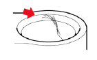
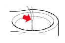
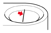
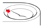
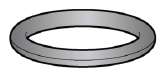
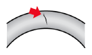
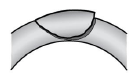
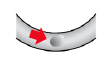
O-RING ABNORMALITIES
TABLE 2
| OK CONDITION | There are NO cuts, dents, crushed areas, foreign materials, or twists. | ||||
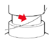
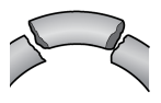
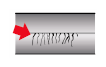
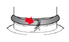
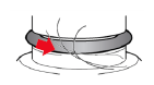
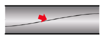
| CUT | |||||
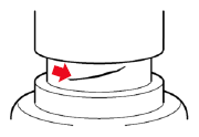
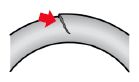
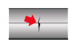
| DENT/CRUSHED AREA | |||||
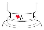
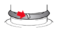
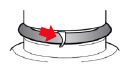
| FOREIGN MATERIAL | Metal Fragment | Resin Fragment | Lint | Hair | |
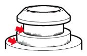
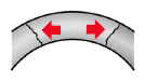
| TWIST | |||||
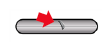
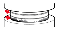
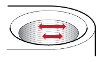
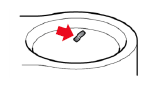
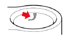
SEALING SURFACE ABNORMALITIES (O-RING ATTACHMENT AREA)
TABLE 3
| OK CONDITION | Processing evidence in circumferential direction is NOT a cause of leakage. | |||
| FOREIGN MATERIAL | Metal Fragment | Resin Fragment | Lint | Hair |
| DAMAGE | ||||
| CORROSION | White and Yellow Materials Adhered (Corrosion Product) | Damage (Scratches) in Axial Direction and Discoloration (Black) | ||