Installation [11/2023 - ]: Procedure
- INSTALL TIE ROD ASSEMBLY LH
- INSTALL TIE ROD ASSEMBLY RH
HINT:
Perform the same procedure as for the LH side.
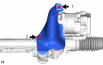
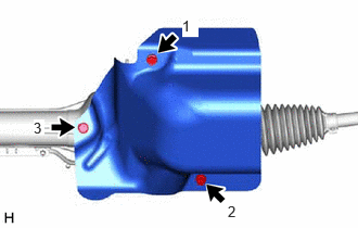
- INSTALL RACK AND PINION POWER STEERING GEAR ASSEMBLY
- Install the rack and pinion power steering gear assembly to the front frame assembly with the 4 bolts and 4 new nuts.
Torque: 88 N.m (897 kgf/cm, 65 ft.lbf)
NOTE:Because the nut has its own stopper, do not turn the nut. Tighten the bolt with the nut secured.
- Install the rack and pinion power steering gear assembly to the front frame assembly with the 4 bolts and 4 new nuts.
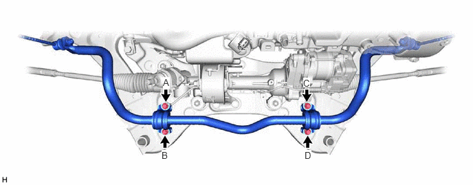
- INSTALL FRONT STABILIZER BAR SUB-ASSEMBLY WITH LINK
- Install the front stabilizer bar sub-assembly with the 2 front stabilizer links to the front frame assembly with the 4 bolts.
Torque: 50 N.m (510 kgf/cm, 37 ft.lbf)
NOTE:Temporarily tighten the bolts in the order of (D), (C) and (B), and then fully tighten the 4 bolts in the order of (A), (B), (C), and (D).
- Install the front stabilizer bar sub-assembly with the 2 front stabilizer links to the front frame assembly with the 4 bolts.
- INSTALL FRONT FRAME ASSEMBLY
Refer to PROCEDURE - Step 6
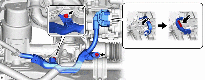
- CONNECT WIRE HARNESS
- Install the wire harness to the rack and pinion power steering gear assembly with the 2 bolts.
Torque: 10 N.m (102 kgf/cm, 7 ft.lbf)
- Connect the wire harness connector to the rack and pinion power steering gear assembly.
HINT:
Make sure that the connector is fully inserted before rotating the lock lever to engage the lock.
- Install the wire harness to the rack and pinion power steering gear assembly with the 2 bolts.
- INSTALL STEERING GEAR HEAT INSULATOR
- for A25A-FXS:
- for T24A-FTS:
- INSTALL ENGINE ASSEMBLY WITH TRANSAXLE
for A25A-FXS: Refer to PROCEDURE - Step 21
for T24A-FTS: Refer to PROCEDURE - Step 31
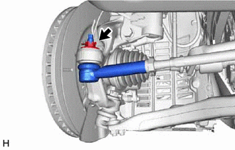
- CONNECT TIE ROD ASSEMBLY LH
- CONNECT TIE ROD ASSEMBLY RH
HINT:
Perform the same procedure as for the LH side.
- CONNECT STEERING INTERMEDIATE SHAFT ASSEMBLY
- INSTALL FRONT WHEELS
Refer to PROCEDURE - Step 1
- INSPECT AND ADJUST FRONT WHEEL ALIGNMENT
Refer to ADJUSTMENT [11/2023 - 11/2024] , or refer to ADJUSTMENT [11/2024 - ]
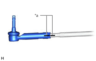
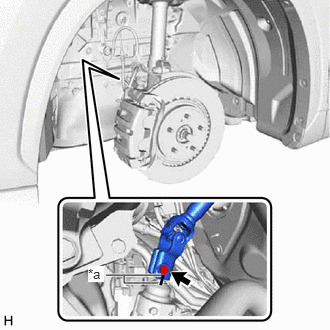
- FULLY TIGHTEN TIE ROD ASSEMBLY LH
- Using SST, tighten the tie rod assembly LH lock nuts.
- SST: 09612-24014
- 09617-24011
Specified Tightening Torque
Torque: 88 N.m (897 kgf/cm, 65 ft.lbf)
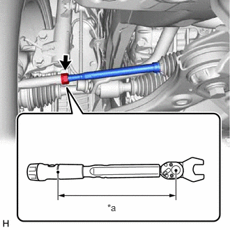
*a Torque Wrench Fulcrum Length HINT:
- Calculate the torque wrench reading when changing the fulcrum length of the torque wrench.
Refer to PRECAUTION [11/2023 - ]
- When using SST (fulcrum length of 52 mm (2.05 in.)) + torque wrench (fulcrum length of 255 mm (10.04 in.)): 73 N.m (744 kgf/cm, 54 ft.lbf)
- SST: 09612-24014
- Using SST, tighten the tie rod assembly LH lock nuts.
- FULLY TIGHTEN TIE ROD ASSEMBLY RH
HINT:
Perform the same procedure as for the LH side.
- UPDATE ECU SECURITY KEY
- If the rack and pinion power steering gear assembly has been replaced, perform Update ECU security key.
Refer to UPDATE ECU SECURITY KEY [11/2023 - ]
- If the rack and pinion power steering gear assembly has been replaced, perform Update ECU security key.
- ECU CONFIGURATION
- If the rack and pinion power steering gear assembly has been replaced, perform ECU configuration.
Refer to ECU CONFIGURATION [11/2023 - ]
- If the rack and pinion power steering gear assembly has been replaced, perform ECU configuration.
- POWER STEERING ECU INITIAL SETTING
Refer to CALIBRATION [11/2023 - ]