Adjustment [12/2019 - ]: Procedure
- STEERING WHEEL OFF CENTER ADJUSTMENT PROCEDURE
- Inspect steering wheel off center.
- Turn the steering wheel assembly to the center position.
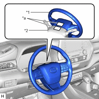
- Apply masking tape to the top center of the steering wheel assembly and upper steering column cover.
*1 Steering Wheel Assembly *2 Upper Steering Column Cover *a Masking Tape - Drive the vehicle in a straight line for 100 m (328 ft.) at a constant speed of 56 km/h (35 mph), while holding the steering wheel assembly to maintain the course.
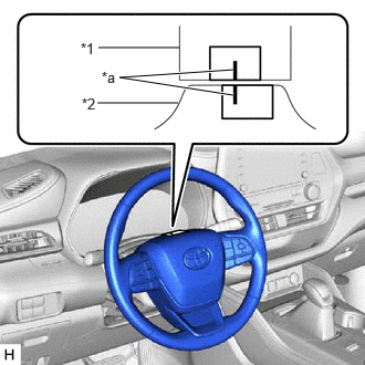
- Draw a line on the masking tape as shown in the illustration.
*1 Upper Steering Column Cover *2 Steering Wheel Assembly *a Marked Line - Turn the steering wheel assembly to the center position.
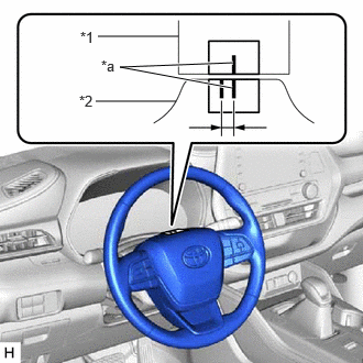
- Draw a new line on the masking tape on the steering wheel assembly as shown in the illustration.
*1 Upper Steering Column Cover *2 Steering Wheel Assembly *a Marked Line - Measure the distance between the 2 lines on the masking tape on the steering wheel assembly.
- Convert the measured distance to the steering angle.
HINT:
- Measured distance of 1 mm (0.0394 in.) = Steering angle of approximately 1 degree
- Make a note of the steering angle.
- Adjust the steering angle.
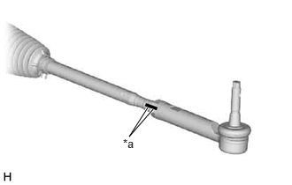
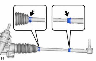
- Put matchmarks on the tie rod assemblies LH and RH and steering rack end sub-assembly respectively.
*a Matchmark - Using a paper gauge, measure the thread length of the steering rack end sub-assemblies.
HINT:
- Measure both RH and LH sides.
- Make a note of the measured values.
- Remove the steering rack boot clips from the RH and LH steering rack boots.
- Loosen the RH and LH lock nuts.
- Turn the RH and LH steering rack end sub-assemblies by the same amount (but in different directions) according to the measured steering angle.
HINT:
One 360 degree turn of a steering rack end sub-assembly (1.5 mm (0.0591 in.) horizontal movement) equals 9.6 degrees of steering angle.
- Tighten the RH and LH lock nuts to the specified torque.
Refer to PROCEDURE - Step 15 [12/2019 - 10/2022] , or refer to PROCEDURE - Step 14 [10/2022 - 11/2023] , or refer to PROCEDURE - Step 14 [11/2023 - ]
NOTE:Make sure that the difference in thread length between the RH and LH steering rack end sub-assemblies is within 1.5 mm (0.0591 in.).
- Install the RH and LH steering rack boot clips.
Refer to PROCEDURE - Step 5
- Put matchmarks on the tie rod assemblies LH and RH and steering rack end sub-assembly respectively.
- Inspect steering wheel off center.