Removal [12/2019 - 10/2022]: Procedure
- PRECAUTION
- When handling the rack and pinion power steering gear assembly:
- Do not subject the rack and pinion power steering gear assembly (especially the motor and torque sensor) to any impact. Replace the rack and pinion power steering gear assembly with a new one if subjected to a strong impact.
- Do not pull the wire harness when moving the rack and pinion power steering gear assembly.
- When the rack and pinion power steering gear assembly has been replaced, perform assist map writing and torque sensor zero point calibration.
Refer to CALIBRATION [12/2019 - 11/2023]
- When disconnecting or reconnecting the connectors:
- Before disconnecting connectors related to the power steering system, turn the ignition switch to ON, center the steering wheel, turn the ignition switch off, and then disconnect the connectors.
- Before reconnecting connectors related to the power steering system, ensure that the ignition switch is off. Then center the steering wheel and turn the ignition switch to ON.NOTE:
Do not turn the ignition switch to ON when the steering wheel is not centered.
- If the above operations are not carried out properly, the steering center point (zero point) will deviate, which may lead to a difference in steering effort between turning right and left.
HINT:
If there is a difference in steering effort between turning right and left, perform torque sensor zero point calibration.
Refer to CALIBRATION [12/2019 - 11/2023]
- When handling the rack and pinion power steering gear assembly:
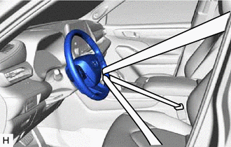
- ALIGN FRONT WHEELS FACING STRAIGHT AHEAD
- SECURE STEERING WHEEL
- REMOVE FRONT WHEELS
Refer to PROCEDURE - Step 1
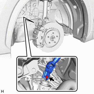
- SEPARATE STEERING INTERMEDIATE SHAFT ASSEMBLY
- Remove the bolt and slide the steering intermediate shaft assembly.NOTE:
Do not separate the steering intermediate shaft assembly from the rack and pinion power steering gear assembly.
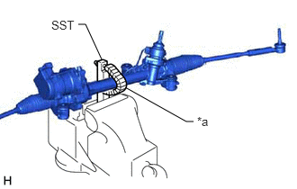
*a Matchmark - Put matchmarks on the rack and pinion power steering gear assembly and steering intermediate shaft assembly.
- Separate the steering intermediate shaft assembly from the rack and pinion power steering gear assembly.
- Remove the bolt and slide the steering intermediate shaft assembly.
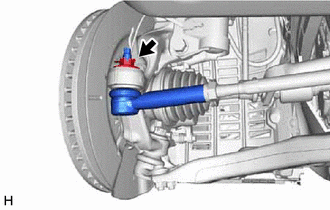
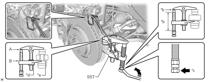
- SEPARATE TIE ROD ASSEMBLY LH
- Remove the cotter pin and nut.
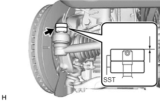
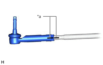
- Install SST to the tie rod assembly LH as shown in the illustration.
- SST: 09960-20010
- 09961-02060
NOTE:Make sure that the upper ends of the tie rod assembly LH and SST are aligned.
- SST: 09960-20010
- Using SST, separate the tie rod assembly LH from the steering knuckle LH as shown in the illustration.
- SST: 09960-20010
- 09961-02010
*a String *b Molybdenum Grease Application Area *c Place wrench here *d Center Nut *e Spacer - - 
Turn - - WARNING:Apply molybdenum grease to the threads and end of the SST bolt.
NOTE:- Be sure to tighten the string firmly to secure SST to the steering knuckle LH to prevent SST from falling off.
- Install SST with the center nut so that (A) and (B) shown in the illustration are parallel. Otherwise, the ball joint dust cover may be damaged.
- Be sure to place the wrench on the part shown in the illustration.
- Do not damage the front disc brake dust cover.
- Do not damage the ball joint dust cover.
- Do not damage the steering knuckle LH.
- Make sure that SST is securely positioned on the spacer.
- If the steering knuckle spacer has come off, replace the steering knuckle with a new one.
- SST: 09960-20010
- Remove the cotter pin and nut.
- SEPARATE TIE ROD ASSEMBLY RH
HINT:
Perform the same procedure as for the LH side.
- REMOVE ENGINE ASSEMBLY WITH TRANSAXLE
for A25A-FXS: Refer to REMOVAL [12/2019 - 10/2022]
for 2GR-FKS: Refer to REMOVAL [12/2019 - 09/2020] , or refer to REMOVAL [09/2020 - 10/2022]
- REMOVE STEERING GEAR HEAT INSULATOR
- DISCONNECT WIRE HARNESS
- REMOVE FUEL DELIVERY GUARD (for A25A-FXS)
Refer to PROCEDURE - Step 40
- INSTALL ENGINE HANGERS
for A25A-FXS: Refer to PROCEDURE - Step 41
for 2GR-FKS: Refer to PROCEDURE - Step 61 [12/2019 - 09/2020] , or refer to PROCEDURE - Step 61 [09/2020 - 10/2022]
- REMOVE FRONT FRAME ASSEMBLY
Refer to PROCEDURE - Step 6
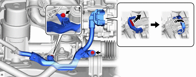
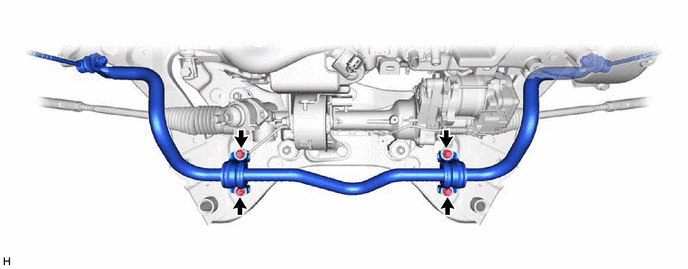
- REMOVE FRONT STABILIZER BAR SUB-ASSEMBLY WITH LINK
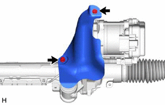
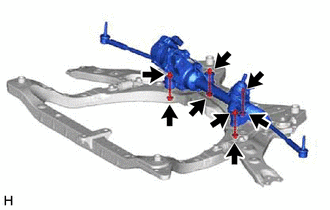
- REMOVE RACK AND PINION POWER STEERING GEAR ASSEMBLY
- SECURE RACK AND PINION POWER STEERING GEAR ASSEMBLY
- REMOVE TIE ROD ASSEMBLY LH
- REMOVE TIE ROD ASSEMBLY RH
HINT:
Perform the same procedure as for the LH side.