Drive Mode Select Switch Circuit [12/2019 - 10/2022]: Procedure
- CHECK CAN COMMUNICATION SYSTEM
- Check for DTCs.
Refer to HOW TO PROCEED WITH TROUBLESHOOTING [12/2019 - 10/2022]
Result
Result Proceed to CAN communication system DTCs are not output. A CAN communication system DTCs are output. B
Result:
B
GO TO CAN COMMUNICATION SYSTEM. Refer to HOW TO PROCEED WITH TROUBLESHOOTING [12/2019 - 10/2022]
Result:
A
See step 2
- Check for DTCs.
- CHECK HARNESS AND CONNECTOR (DRIVE MODE SELECT SWITCH (NO. 1 PATTERN SELECT SWITCH ASSEMBLY) - BODY GROUND)
- Turn the engine switch off.
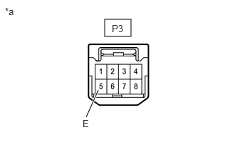
- Disconnect the P3 drive mode select switch (No. 1 pattern select switch assembly) connector.
*a Front view of wire harness connector
(to Drive Mode Select Switch (No. 1 Pattern Select Switch Assembly)) - Measure the resistance according to the value(s) in the table below.
Standard Resistance
Tester Connection Condition Specified Condition P3-5 (E) - Body ground Always Below 1 Ω Result
Proceed to OK NG
Result:
NG
REPAIR OR REPLACE HARNESS OR CONNECTOR
Result:
OK
See step 3
- INSPECT DRIVE MODE SELECT SWITCH (NO. 1 PATTERN SELECT SWITCH ASSEMBLY)
- Inspect drive mode select switch (No. 1 pattern select switch assembly).
UA80E: Refer to INSPECTION [12/2019 - 10/2022]
UA80F: Refer to INSPECTION [12/2019 - 10/2022]
OK
Drive mode select switch (No. 1 pattern select switch assembly) is normal.
Result
Result Proceed to Drive mode select switch (No. 1 pattern select switch assembly) is normal. A Drive mode select switch (No. 1 pattern select switch assembly) is abnormal. B
Result:
B
REPLACE NO. 1 PATTERN SELECT SWITCH ASSEMBLY
UA80E: Refer to REMOVAL [12/2019 - 10/2022]
UA80F: Refer to REMOVAL [12/2019 - 10/2022]
Result:
A
See step 4
- Inspect drive mode select switch (No. 1 pattern select switch assembly).
- CHECK HARNESS AND CONNECTOR (DRIVE MODE SELECT SWITCH (NO. 1 PATTERN SELECT SWITCH ASSEMBLY) - ECM)
- Connect the P3 drive mode select switch (No. 1 pattern select switch assembly) connector.
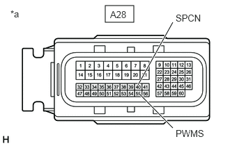
- Disconnect the A28 ECM connectors.
*a Front view of wire harness connector
(to ECM) - Measure the resistance according to the value(s) in the table below.
Standard Resistance
Tester Connection Condition Specified Condition A28-55 (PWMS) - Body ground SPORT mode switch being turned and held Below 1 Ω A28-55 (PWMS) - Body ground SPORT mode switch not turned 10 kΩ or higher A28-40 (SPCN) - Body ground NORMAL mode switch being pushed and held Below 1 Ω A28-40 (SPCN) - Body ground NORMAL mode switch not pushed 10 kΩ or higher Result
Proceed to OK NG
Result:
OK
REPLACE ECM. Refer to REMOVAL [12/2019 - 09/2020] , or refer to REMOVAL [09/2020 - 10/2022]
Result:
NG
REPAIR OR REPLACE HARNESS OR CONNECTOR