Terminals Of Ecu [11/2023 - ]
- CHECK MAIN BODY ECU (MULTIPLEX NETWORK BODY ECU) AND INSTRUMENT PANEL JUNCTION BLOCK ASSEMBLY
- Remove the main body ECU (multiplex network body ECU) from the power distribution box assembly.
Refer to REMOVAL [11/2023 - ]
- Measure the voltage and resistance according to the value(s) in the table below.
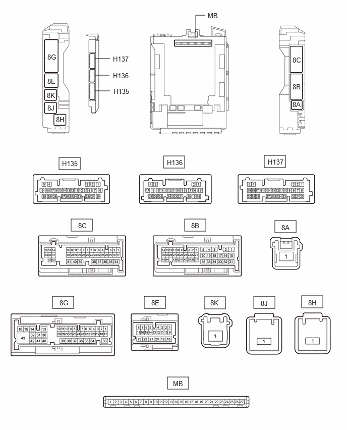
Terminal No. (Symbol) Terminal Description Condition Specified Condition MB-13 (GND1) - Body ground Ground Always Below 1 Ω MB-26 (BECU) - Body ground Auxiliary battery power supply Ignition switch off 11 to 14 V MB-27 (IGR) - Body ground IG power supply Ignition switch ON 11 to 14 V Ignition switch off Below 1 V MB-14 (GND2) - Body ground Ground Always Always - Reconnect the power distribution box assembly connectors.
- Measure the voltage according to the value(s) in the table below.
Terminal No. (Symbol) Terminal Description Condition Specified Condition 8G-4 - Body ground Rear center seat belt buckle switch signal Rear center seat belt fastened Below 1 V Rear center seat belt unfastened 11 to 14 V 8G-8 - Body ground Rear RH seat belt buckle switch signal Rear RH seat belt fastened Below 1 V Rear RH seat belt unfastened 11 to 14 V 8G-19 - Body ground Rear LH seat belt buckle switch signal Rear LH seat belt fastened Below 1 V Rear LH seat belt unfastened 11 to 14 V 8G-24 - Body ground Rear door courtesy light switch (for LH) input Rear door LH open Below 1 V Rear door LH closed 11 to 14 V or pulse output (maximum 14 V) 8G-31 - Body ground Rear door courtesy light switch (for RH) input Rear door RH open Below 1 V Rear door RH closed 11 to 14 V or pulse output (maximum 14 V)
- Remove the main body ECU (multiplex network body ECU) from the power distribution box assembly.
- CHECK COMBINATION METER ASSEMBLY (except 12.3 Inch Display)
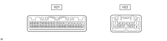
- Disconnect the H21 combination meter assembly connector.
- Measure the voltage and resistance according to the value(s) in the table below.
Terminal No. (Symbol) Terminal Description Condition Specified Condition H21-40 (B) - Body ground Auxiliary battery power supply Ignition switch off 11 to 14 V H21-39 (IG+) - Body ground Ignition power supply Ignition switch off Below 1 V Ignition switch ON 11 to 14 V H21-21 (ES) - Body ground Ground Always Below 1 Ω H21-24 (RLBT) - Body ground Rear No. 2 seat belt LH buckle switch signal Rear No. 2 seat belt LH fastened 10 kΩ or higher Rear No. 2 seat belt LH unfastened Below 1 Ω H21-25 (RCBT) - Body ground Rear No. 2 seat belt center buckle switch signal Rear No. 2 seat belt center fastened 10 kΩ or higher Rear No. 2 seat belt center unfastened Below 1 Ω H21-26 (RRBT) - Body ground Rear No. 2 seat belt RH buckle switch signal Rear No. 2 seat belt RH fastened 10 kΩ or higher Rear No. 2 seat belt RH unfastened Below 1 Ω
- CHECK COMBINATION METER ASSEMBLY (for 12.3 Inch Display)
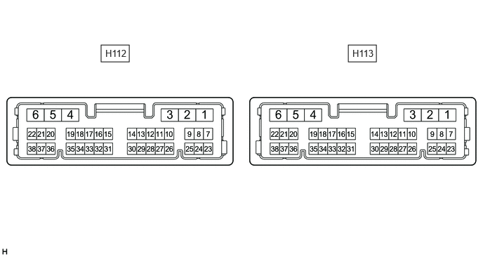
- Disconnect the H112 combination meter assembly connector.
- Measure the voltage and resistance according to the value(s) in the table below.
Terminal No. (Symbol) Terminal Description Condition Specified Condition H112-5 (B) - Body ground Auxiliary battery power supply Ignition switch off 11 to 14 V H112-6 (IG+) - Body ground Ignition power supply Ignition switch off Below 1 V Ignition switch ON 11 to 14 V H112-2 (ES) - Body ground Ground Always Below 1 Ω H112-38 (RLBT) - Body ground Rear No. 2 seat belt LH buckle switch signal Rear No. 2 seat belt LH fastened 10 kΩ or higher Rear No. 2 seat belt LH unfastened Below 1 Ω H112-19 (RCBT) - Body ground Rear No. 2 seat belt center buckle switch signal Rear No. 2 seat belt center fastened 10 kΩ or higher Rear No. 2 seat belt center unfastened Below 1 Ω H112-35 (RRBT) - Body ground Rear No. 2 seat belt RH buckle switch signal Rear No. 2 seat belt RH fastened 10 kΩ or higher Rear No. 2 seat belt RH unfastened Below 1 Ω
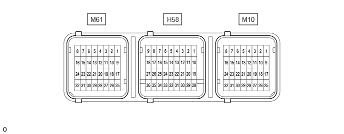
- CHECK AIRBAG SENSOR ASSEMBLY
Terminal No. Terminal Symbol Destination M61-24 GNDL Front seat inner belt assembly LH M61-30 LBE+ M10-18 GNDR Front seat inner belt assembly RH M10-27 RBE+ M10-24 SVC Occupant classification sensor M10-31 SGD M10-32 SIG