DTC P21CF-13: Cylinder 1 Injector "B" Circuit Open; DTC P21D0-13: Cylinder 2 Injector "B" Circuit Open; DTC P21D1-13: Cylinder 3 Injector "B" Circuit Open; DTC P21D2-13: Cylinder 4 Injector "B" Circuit Open; DTC P21D3-13: Cylinder 5 Injector "B" Circuit Open; DTC P21D4-13: Cylinder 6 Injector "B" Circuit Open [12/2019 - 10/2022]: Procedure
- CHECK DTCS OUTPUT (IN ADDITION TO DTC P21CF-13, P21D0-13, P21D1-13, P21D2-13, P21D3-13 OR P21D4-13)
- Read the DTCs.
Powertrain > Engine > Trouble Codes
Result
Result Proceed to P21CF-13, P21D0-13, P21D1-13, P21D2-13, P21D3-13 or P21D4-13 is output A P21CF-13, P21D0-13, P21D1-13, P22D2-13, P21D3-13 and P21D4-13 are output B
Result:
B
REPAIR OR REPLACE HARNESS OR CONNECTOR (IG2 NO. 1 RELAY - FUEL INJECTOR ASSEMBLY (FOR PORT INJECTION))
Result:
A
See step 2
- Read the DTCs.
- CHECK TERMINAL VOLTAGE (POWER SOURCE OF FUEL INJECTOR ASSEMBLY (FOR PORT INJECTION))
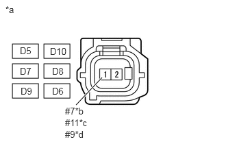
*a Front view of wire harness connector
(to Fuel Injector Assembly (for Port Injection))*b No. 1 Cylinder or No. 6 Cylinder *c No. 2 Cylinder or No. 5 Cylinder *d No. 3 Cylinder or No. 4 Cylinder - Disconnect the fuel injector assembly (for port injection) connector.
- Turn the ignition switch to ON.
- Measure the voltage according to the value(s) in the table below
Standard Voltage
Tester Connection Condition Specified Condition D5-1 (#7) - Body ground Ignition switch ON 11 to 14 V D10-1 (#7) - Body ground Ignition switch ON 11 to 14 V D7-1 (#9) - Body ground Ignition switch ON 11 to 14 V D8-1 (#9) - Body ground Ignition switch ON 11 to 14 V D9-1 (#11) - Body ground Ignition switch ON 11 to 14 V D6-1 (#11) - Body ground Ignition switch ON 11 to 14 V Result
Proceed to OK NG
Result:
NG
REPAIR OR REPLACE HARNESS OR CONNECTOR (IG2 NO. 1 RELAY - FUEL INJECTOR ASSEMBLY (FOR PORT INJECTION))
Result:
OK
See step 3
- CHECK HARNESS AND CONNECTOR (FUEL INJECTOR ASSEMBLY (FOR PORT INJECTION) - ECM)
- Disconnect the fuel injector assembly (for port injection) connector.
- Disconnect the ECM connector.
- Measure the resistance according to the value(s) in the table below.
Standard Resistance
Tester Connection Condition Specified Condition D5-2 (#70) - C54-45 (#10) Always Below 1 Ω D10-2 (#70) - C54-40 (#60) Always Below 1 Ω D7-2 (#90) - C54-41 (#30) Always Below 1 Ω D8-2 (#90) - C54-44 (#40) Always Below 1 Ω D9-2 (#110) - C54-42 (#50) Always Below 1 Ω D6-2 (#110) - C54-43 (#20) Always Below 1 Ω D5-2 (#70) or C54-45 (#10) - Body ground and other terminals Always 10 kΩ or higher D10-2 (#70) or C54-40 (#60) - Body ground and other terminals Always 10 kΩ or higher D7-2 (#90) or C54-41 (#30) - Body ground and other terminals Always 10 kΩ or higher D8-2 (#90) or C54-44 (#40) - Body ground and other terminals Always 10 kΩ or higher D9-2 (#110) or C54-42 (#50) - Body ground and other terminals Always 10 kΩ or higher D6-2 (#110) or C54-43 (#20) - Body ground and other terminals Always 10 kΩ or higher Result
Proceed to OK NG
Result:
NG
REPAIR OR REPLACE HARNESS OR CONNECTOR
Result:
OK
See step 4
- INSPECT FUEL INJECTOR ASSEMBLY (FOR PORT INJECTION (RESISTANCE))
Refer to INSPECTION [12/2019 - 10/2022]
HINT:
Perform "Inspection After Repair" after replacing the fuel injector assembly (for port injection).
Refer to INITIALIZATION [12/2019 - 10/2022]
Result
Proceed to OK NG Result:
OK
REPLACE ECM. Refer to REMOVAL [12/2019 - 09/2020] , or refer to REMOVAL [09/2020 - 10/2022]
Result:
NG
REPLACE FUEL INJECTOR ASSEMBLY (FOR PORT INJECTION). Refer to REMOVAL [12/2019 - 10/2022]