DTC P2237-11: A/F (O2) Sensor Positive Current Control Bank 1 Sensor 1 Circuit Short to Ground; DTC P2237-12: A/F (O2) Sensor Positive Current Control Bank 1 Sensor 1 Circuit Short to Battery; DTC P2237-13: A/F (O2) Sensor Positive Current Control Bank 1 Sensor 1 Circuit Open; DTC P2237-16: A/F (O2) Sensor Positive Current Control Bank 1 Sensor 1 Circuit Voltage Below Threshold; DTC P2237-17: A/F (O2) Sensor Positive Current Control Bank 1 Sensor 1 Circuit Voltage Above Threshold; DTC P2237-1B: A/F (O2) Sensor Positive Current Control Bank 1 Sensor 1 Circuit Resistance Above Threshold; DTC P2240-11: A/F (O2) Sensor Positive Current Control Bank 2 Sensor 1 Circuit Short to Ground; DTC P2240-12: A/F (O2) Sensor Positive Current Control Bank 2 Sensor 1 Circuit Short to Battery; DTC P2240-13: A/F (O2) Sensor Positive Current Control Bank 2 Sensor 1 Circuit Open; DTC P2240-16: A/F (O2) Sensor Positive Current Control Bank 2 Sensor 1 Circuit Voltage Below Threshold; DTC P2240-17: A/F (O2) Sensor Positive Current Control Bank 2 Sensor 1 Circuit Voltage Above Threshold; DTC P2240-1B: A/F (O2) Sensor Positive Current Control Bank 2 Sensor 1 Circuit Resistance Above Threshold; DTC P2251-11: O2 Sensor Negative Current Control Bank 1 Sensor 1 Circuit Short to Ground; DTC P2251-12: O2 Sensor Negative Current Control Bank 1 Sensor 1 Circuit Short to Battery; DTC P2254-11: O2 Sensor Negative Current Control Bank 2 Sensor 1 Circuit Short to Ground; DTC P2254-12: O2 Sensor Negative Current Control Bank 2 Sensor 1 Circuit Short to Battery [12/2019 - 10/2022]: Procedure
- CHECK TERMINAL VOLTAGE (AIR FUEL RATIO SENSOR VOLTAGE)
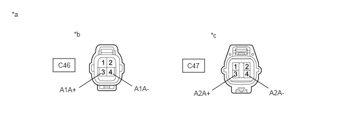
*a Front view of wire harness connector
(to Air Fuel Ratio Sensor)*b Bank 1 *c Bank 2 - - HINT:
Make sure that the connector is properly connected. If it is not, securely connect it and check for DTCs again.
- Disconnect the air fuel ratio sensor connector.
- Turn the ignition switch to ON.
- Measure the voltage according to the value(s) in the table below.
Standard Voltage
Tester Connection Condition Specified Condition C46-3 (A1A+) - Body ground Ignition switch ON 3.2 to 3.4 V C46-4 (A1A-) - Body ground Ignition switch ON 2.8 to 3.0 V C46-3 (A1A+) - C46-4 (A1A-) Ignition switch ON 0.2 to 0.6 V C47-3 (A2A+) - Body ground Ignition switch ON 3.2 to 3.4 V C47-4 (A2A-) - Body ground Ignition switch ON 2.8 to 3.0 V C47-3 (A2A+) - C47-4 (A2A-) Ignition switch ON 0.2 to 0.6 V HINT:
Perform "Inspection After Repair" after replacing the air fuel ratio sensor.
Refer to INITIALIZATION [12/2019 - 10/2022]
Result
Proceed to OK NG
Result:
OK
REPLACE AIR FUEL RATIO SENSOR. Refer to REMOVAL [12/2019 - 10/2022]
Result:
NG
See step 2
- CHECK HARNESS AND CONNECTOR (AIR FUEL RATIO SENSOR - ECM)
- Disconnect the air fuel ratio sensor connector.
- Disconnect the ECM connector.
- Measure the resistance according to the value(s) in the table below.
Standard Resistance
Tester Connection Condition Specified Condition C46-1 (HA1A) - C54-52 (HA1A) Always Below 1 Ω C46-3 (A1A+) - C54-125 (A1A+) Always Below 1 Ω C46-4 (A1A-) - C54-126 (A1A-) Always Below 1 Ω C47-1 (HA2A) - C54-17 (HA2A) Always Below 1 Ω C47-3 (A2A+) - C54-123 (A2A+) Always Below 1 Ω C47-4 (A2A-) - C54-124 (A2A-) Always Below 1 Ω C46-1 (HA1A) or C54-52 (HA1A) - Body ground and other terminals Always 10 kΩ or higher C46-3 (A1A+) or C54-125 (A1A+) - Body ground and other terminals Always 10 kΩ or higher C46-4 (A1A-) or C54-126 (A1A-) - Body ground and other terminals Always 10 kΩ or higher C47-1 (HA2A) or C54-17 (HA2A) - Body ground and other terminals Always 10 kΩ or higher C47-3 (A2A+) or C54-123 (A2A+) - Body ground and other terminals Always 10 kΩ or higher C47-4 (A2A-) or C54-124 (A2A-) - Body ground and other terminals Always 10 kΩ or higher Result
Proceed to OK NG
Result:
OK
REPLACE ECM. Refer to REMOVAL [12/2019 - 09/2020] , or refer to REMOVAL [09/2020 - 10/2022]
Result:
NG
REPAIR OR REPLACE HARNESS OR CONNECTOR