DTC P0504-2B: Brake Switch "A"/"B" Signal Cross Coupled [12/2019 - 10/2022]: Procedure
- CHECK TERMINAL VOLTAGE (POWER SOURCE OF STOP LIGHT SWITCH ASSEMBLY)
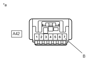
*a Front view of wire harness connector
(to Stop Light Switch Assembly)- Disconnect the stop light switch assembly connector.
- Measure the voltage according to the value(s) in the table below.
Standard Voltage
Tester Connection Condition Specified Condition A42-7 (B) - Body ground Always 11 to 14 V Result
Proceed to OK NG
Result:
NG
See step 11
Result:
OK
See step 2
- CHECK TERMINAL VOLTAGE (POWER SOURCE OF STOP LIGHT SWITCH ASSEMBLY)
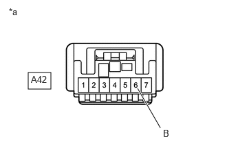
*a Front view of wire harness connector
(to Stop Light Switch Assembly)- Disconnect the stop light switch assembly connector.
- Turn the ignition switch to ON.
- Measure the voltage according to the value(s) in the table below.
Standard Voltage
Tester Connection Condition Specified Condition A42-6 (B) - Body ground Ignition switch ON 11 to 14 V Result
Proceed to OK NG
Result:
NG
See step 6
Result:
OK
See step 3
- CHECK HARNESS AND CONNECTOR (STOP LIGHT SWITCH ASSEMBLY - BODY GROUND)
- Disconnect the stop light switch assembly connector.
- Measure the resistance according to the value(s) in the table below.
Standard Resistance
Tester Connection Condition Specified Condition A42-2 (GND) - Body ground Always Below 1 Ω Result
Proceed to OK NG
Result:
NG
REPAIR OR REPLACE HARNESS OR CONNECTOR
Result:
OK
See step 4
- CHECK TERMINAL VOLTAGE (STP AND ST1- VOLTAGE)
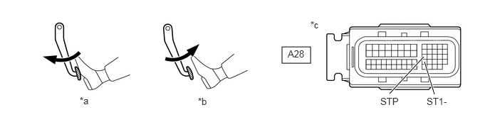
*a Brake Pedal Depressed *b Brake Pedal Released *c Front view of wire harness connector
(to ECM)- - - Disconnect the ECM connector.
- Turn the ignition switch to ON.
- Measure the voltage according to the value(s) in the table below.
Standard Voltage
Tester Connection Brake Pedal Operation Specified Condition A28-42 (ST1-) - Body ground Released 7.5 to 14 V Depressed Below 1.5 V A28-27 (STP) - Body ground Released Below 1.5 V Depressed 7.5 to 14 V Result
Proceed to OK NG
Result:
OK
REPLACE ECM. Refer to REMOVAL [12/2019 - 09/2020] , or refer to REMOVAL [09/2020 - 10/2022]
Result:
NG
See step 5
- CHECK HARNESS AND CONNECTOR (STOP LIGHT SWITCH ASSEMBLY - ECM)
- Disconnect the stop light switch assembly connector.
- Disconnect the ECM connector.
- Measure the resistance according to the value(s) in the table below.
Standard Resistance
Tester Connection Condition Specified Condition A42-5 (L) - A28-42 (ST1-) Always Below 1 Ω A42-3 (L) - A28-27 (STP) Always Below 1 Ω A42-5 (L) or A28-42 (ST1-) - Body ground and other terminals Always 10 kΩ or higher A42-3 (L) or A28-27 (STP) - Body ground and other terminals Always 10 kΩ or higher Result
Proceed to OK NG
Result:
OK
REPLACE STOP LIGHT SWITCH ASSEMBLY. Refer to REMOVAL [12/2019 - ]
Result:
NG
REPAIR OR REPLACE HARNESS OR CONNECTOR
- CHECK HARNESS AND CONNECTOR (INSTRUMENT PANEL JUNCTION BLOCK ASSEMBLY - STOP LIGHT SWITCH ASSEMBLY)
- Disconnect the instrument panel junction block assembly connector.
- Disconnect the stop light switch assembly connector.
- Measure the resistance according to the value(s) in the table below.
Standard Resistance
Tester Connection Condition Specified Condition 4C-15 - A42-6 (B) Always Below 1 Ω 4C-15 or A42-6 (B) - Body ground and other terminals Always 10 kΩ or higher Result
Proceed to OK NG
Result:
NG
REPAIR OR REPLACE HARNESS OR CONNECTOR
Result:
OK
See step 7
- CHECK HARNESS AND CONNECTOR (INSTRUMENT PANEL JUNCTION BLOCK ASSEMBLY - BODY GROUND)
- Disconnect the instrument panel junction block assembly connector.
- Measure the resistance according to the value(s) in the table below.
Standard Resistance
Tester Connection Condition Specified Condition 4B-3 - Body ground Always Below 1 Ω Result
Proceed to OK NG
Result:
NG
REPAIR OR REPLACE HARNESS OR CONNECTOR
Result:
OK
See step 8
- CHECK INSTRUMENT PANEL JUNCTION BLOCK ASSEMBLY (POWER SOURCE)
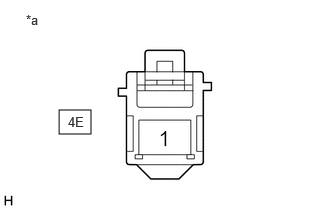
*a Front view of wire harness connector
(to Instrument Panel Junction Block Assembly)- Disconnect the instrument panel junction block assembly connector.
- Measure the voltage according to the value(s) in the table below.
Standard Voltage
Tester Connection Condition Specified Condition 4E-1 - Body ground Always 11 to 14 V Result
Proceed to OK NG
Result:
NG
REPAIR OR REPLACE HARNESS OR CONNECTOR (BATTERY - INSTRUMENT PANEL JUNCTION BLOCK ASSEMBLY)
Result:
OK
See step 9
- CHECK HARNESS AND CONNECTOR (INSTRUMENT PANEL JUNCTION BLOCK ASSEMBLY - CERTIFICATION ECU (SMART KEY ECU ASSEMBLY))
- Disconnect the instrument panel junction block assembly connector.
- Disconnect the certification ECU (smart key ECU assembly) connector.
- Measure the resistance according to the value(s) in the table below.
Standard Resistance
Tester Connection Condition Specified Condition 4A-17 - H48-17 (IG1D) Always Below 1 Ω 4A-17 or H48-17 (IG1D) - Body ground and other terminals Always 10 kΩ or higher Result
Proceed to OK NG
Result:
NG
REPAIR OR REPLACE HARNESS OR CONNECTOR
Result:
OK
See step 10
- CHECK SMART KEY SYSTEM
- Check the smart key system.
Refer to HOW TO PROCEED WITH TROUBLESHOOTING [12/2019 - 10/2021] , or refer to HOW TO PROCEED WITH TROUBLESHOOTING [10/2021 - 11/2023]
Result
Proceed to OK NG
Result:
OK
REPLACE INSTRUMENT PANEL JUNCTION BLOCK ASSEMBLY. Refer to REMOVAL [12/2019 - 10/2022]
Result:
NG
REPAIR SMART KEY SYSTEM. Refer to HOW TO PROCEED WITH TROUBLESHOOTING [12/2019 - 10/2021] , or refer to HOW TO PROCEED WITH TROUBLESHOOTING [10/2021 - 11/2023]
- Check the smart key system.
- CHECK HARNESS AND CONNECTOR (INSTRUMENT PANEL JUNCTION BLOCK ASSEMBLY - STOP LIGHT SWITCH ASSEMBLY)
- Disconnect the instrument panel junction block assembly connector.
- Disconnect the stop light switch assembly connector.
- Measure the resistance according to the value(s) in the table below.
Standard Resistance
Tester Connection Condition Specified Condition 4C-3 - A42-7 (B) Always Below 1 Ω 4C-3 or A42-7 (B) - Body ground and other terminals Always 10 kΩ or higher Result
Proceed to OK NG
Result:
NG
REPAIR OR REPLACE HARNESS OR CONNECTOR
Result:
OK
See step 12
- CHECK INSTRUMENT PANEL JUNCTION BLOCK ASSEMBLY (POWER SOURCE)
*a Front view of wire harness connector
(to Instrument Panel Junction Block Assembly)- Disconnect the instrument panel junction block assembly connector.
- Measure the voltage according to the value(s) in the table below.
Standard Voltage
Tester Connection Condition Specified Condition 4E-1 - Body ground Always 11 to 14 V Result
Proceed to OK NG
Result:
OK
REPLACE INSTRUMENT PANEL JUNCTION BLOCK ASSEMBLY. Refer to REMOVAL [12/2019 - 10/2022]
Result:
NG
REPAIR OR REPLACE HARNESS OR CONNECTOR (BATTERY - INSTRUMENT PANEL JUNCTION BLOCK ASSEMBLY)