DTC P0340-11: Camshaft Position Sensor "A" Bank 1 or Single Sensor Circuit Short to Ground; DTC P0340-15: Camshaft Position Sensor "A" Bank 1 or Single Sensor Circuit Short to Battery or Open; DTC P0345-11: Camshaft Position Sensor "A" Bank 2 Circuit Short to Ground; DTC P0345-15: Camshaft Position Sensor "A" Bank 2 Circuit Short to Battery or Open [12/2019 - 10/2022]: Procedure
- CHECK HARNESS AND CONNECTOR
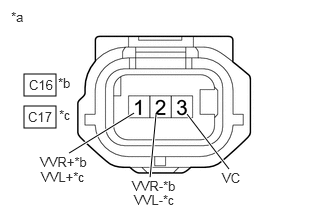
*a Front view of wire harness connector
(to VVT Sensor (for Intake Camshaft))*b Bank 1 *c Bank 2 HINT:
Make sure that the connector is properly connected. If it is not, securely connect it and check for DTCs again.
- Disconnect the VVT sensor (for intake camshaft) connector.
- Turn the ignition switch to ON.
- Measure the voltage according to the value(s) in the table below.
Standard Voltage
Tester Connection Condition Specified Condition C16-3 (VC) - Body ground Ignition switch ON 4.5 to 5.5 V C17-3 (VC) - Body ground Ignition switch ON 4.5 to 5.5 V C16-1 (VVR+) - Body ground Ignition switch ON 3.0 to 5.0 V C17-1 (VVL+) - Body ground Ignition switch ON 3.0 to 5.0 V - Turn the ignition switch off and wait for at least 30 seconds.
- Measure the resistance according to the value(s) in the table below.
Standard Resistance
Tester Connection Condition Specified Condition C16-3 (VC) - C16-1 (VVR+) Ignition switch off 1.425 to 1.575 kΩ C17-3 (VC) - C17-1 (VVL+) Ignition switch off 1.425 to 1.575 kΩ C16-2 (VVR-) - Body ground Always Below 1 Ω C17-2 (VVL-) - Body ground Always Below 1 Ω Result
Proceed to OK NG
Result:
OK
REPLACE VVT SENSOR (FOR INTAKE CAMSHAFT). Refer to REMOVAL [12/2019 - 10/2022]
Result:
NG
See step 2
- CHECK HARNESS AND CONNECTOR (VVT SENSOR (FOR INTAKE CAMSHAFT) - ECM)
- Disconnect the VVT sensor (for intake camshaft) connector.
- Disconnect the ECM connector.
- Measure the resistance according to the value(s) in the table below.
Standard Resistance
Tester Connection Condition Specified Condition C16-1 (VVR+) - C54-132 (VV1+) Always Below 1 Ω C16-2 (VVR-) - C54-100 (VV1-) Always Below 1 Ω C16-3 (VC) - C54-99 (VCV1) Always Below 1 Ω C17-1 (VVL+) - C54-129 (VV2+) Always Below 1 Ω C17-2 (VVL-) - C54-97 (VV2-) Always Below 1 Ω C17-3 (VC) - C54-98 (VCV2) Always Below 1 Ω C16-1 (VVR+) or C54-132 (VV1+) - Body ground and other terminals Always 10 kΩ or higher C16-2 (VVR-) or C54-100 (VV1-) - Body ground and other terminals Always 10 kΩ or higher C16-3 (VC) or C54-99 (VCV1) - Body ground and other terminals Always 10 kΩ or higher C17-1 (VVL+) or C54-129 (VV2+) - Body ground and other terminals Always 10 kΩ or higher C17-2 (VVL-) or C54-97 (VV2-) - Body ground and other terminals Always 10 kΩ or higher C17-3 (VC) or C54-98 (VCV2) - Body ground and other terminals Always 10 kΩ or higher Result
Proceed to OK NG
Result:
OK
REPLACE ECM. Refer to REMOVAL [12/2019 - 09/2020] , or refer to REMOVAL [09/2020 - 10/2022]
Result:
NG
REPAIR OR REPLACE HARNESS OR CONNECTOR