Installation [12/2019 - 10/2022]: Procedure
- INSTALL NO. 1 FUEL TANK CUSHION
HINT:
Perform this procedure only when replacement of the No. 1 fuel tank cushion is necessary.
- Install a new No. 1 fuel tank cushion to the fuel tank sub-assembly.
- INSTALL NO. 6 FUEL TANK CUSHION
HINT:
Perform this procedure only when replacement of the No. 6 fuel tank cushion is necessary.
- Install 3 new No. 6 fuel tank cushions to the fuel tank sub-assembly.
- INSTALL NO. 2 FUEL TUBE CLAMP
- Install the No. 2 fuel tube clamp to the fuel tank breather tube sub-assembly.
- Engage the clamp to install the fuel tank breather tube sub-assembly to the fuel tank sub-assembly.
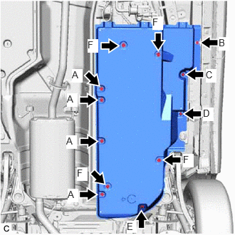
- INSTALL NO. 2 FUEL TANK PROTECTOR
- Install the No. 2 fuel tank protector to the fuel tank sub-assembly with the clip.
- INSTALL NO. 1 FUEL TUBE CLAMP
- Engage the clamp to install the No. 1 fuel tube clamp to the fuel tank sub-assembly.
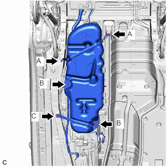
- INSTALL FUEL TANK EVAPORATION VENT TUBE SUB-ASSEMBLY
- Engage the 4 clamps to install the fuel tank evaporation vent tube sub-assembly to the fuel tank sub-assembly.
- INSTALL FUEL TANK MAIN TUBE SUB-ASSEMBLY
- Engage the 3 clamps to install the fuel tank main tube sub-assembly to the fuel tank sub-assembly.
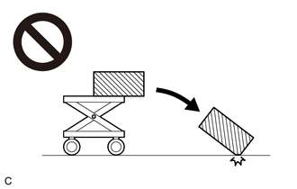
- INSTALL FUEL TANK SUB-ASSEMBLY WARNING:
The fuel tank sub-assembly is very heavy. Be sure to follow the procedure described in the repair information, or the fuel tank sub-assembly may fall off the engine lifter.
- Set the fuel tank sub-assembly on an engine lifter.NOTE:
Using height adjustment attachments and plate lift attachments, keep the fuel tank sub-assembly horizontal.
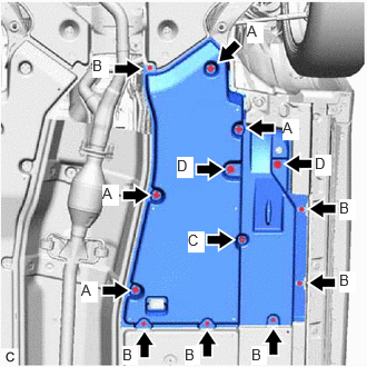
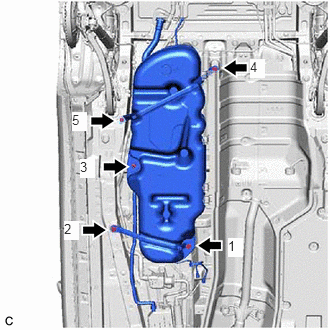
- Using the engine lifter, slowly raise the fuel tank sub-assembly, and then temporarily install the fuel tank sub-assembly, No. 1 fuel tank band sub-assembly and No. 2 fuel tank band sub-assembly with the 5 bolts.
Bolt Length
Bolt Width Across Flats A 14 mm (0.551 in.) B 12 mm (0.472 in.) C 12 mm (0.472 in.) or 14 mm (0.551 in.) NOTE:- Be careful not to drop the fuel tank sub-assembly.
- When installing the fuel tank sub-assembly, tilt it slightly to prevent it from interfering with the surrounding parts.
- Tighten the 5 bolts in the order shown in the illustration.
 Courtesy of © TOYOTA, LICENSE AGREEMENT TMS1002
Torque: 45 N.m (459 kgf/cm, 33 ft.lbf)
- Connect the lower fuel tank filler pipe sub-assembly to the fuel tank filler pipe sub-assembly.
Refer to PRECAUTION [12/2019 - 10/2022]
- Connect the fuel tank breather tube sub-assembly to the fuel tank filler pipe sub-assembly.
Refer to PRECAUTION [12/2019 - 10/2022]
- for 2WD:
- Install the engine service cover assembly and rear main muffler heat insulator sub-assembly to the vehicle body with the nut.
Torque: 4.9 N.m (50 kgf/cm, 43 in.lbf)
- Install the engine service cover assembly and rear main muffler heat insulator sub-assembly to the vehicle body with the nut.
- Set the fuel tank sub-assembly on an engine lifter.
- CONNECT FUEL TANK MAIN TUBE SUB-ASSEMBLY
- Connect the fuel tank main tube sub-assembly to the fuel pipe.
Refer to PRECAUTION [12/2019 - 10/2022]
- Connect the fuel tank main tube sub-assembly to the fuel pipe.
- CONNECT FUEL TANK EVAPORATION VENT TUBE SUB-ASSEMBLY
- Engage the clamp to connect the fuel tank evaporation vent tube sub-assembly to the canister (charcoal canister assembly).
Refer to PRECAUTION [12/2019 - 10/2022]
- Engage the clamp to connect the fuel tank evaporation vent tube sub-assembly to the canister (charcoal canister assembly).
- INSTALL REAR SUSPENSION MEMBER SUB-ASSEMBLY
Refer to INSTALLATION [12/2019 - 10/2022]
- INSTALL NO. 1 FLOOR UNDER COVER
- INSTALL FRONT FLOOR COVER LH
- INSTALL FUEL SUCTION TUBE WITH PUMP AND GAUGE ASSEMBLY
Refer to INSTALLATION [12/2019 - 10/2022]
- ADD FUEL