Removal [12/2019 - 10/2022]: Procedure
- PRECAUTION NOTE:
After turning the ignition switch off, waiting time may be required before disconnecting the cable from the negative (-) battery terminal. Therefore, make sure to read the disconnecting the cable from the negative (-) battery terminal notices before proceeding with work.
Refer to PRECAUTION [12/2019 - 11/2023]
- DISCHARGE FUEL SYSTEM PRESSURE
Refer to PRECAUTION [12/2019 - 10/2022]
- DISCONNECT CABLE FROM NEGATIVE BATTERY TERMINAL NOTE:
When disconnecting the cable, some systems need to be initialized after the cable is reconnected.
Refer to PRECAUTION [12/2019 - 11/2023]
- REMOVE WINDSHIELD WIPER MOTOR AND LINK ASSEMBLY
Refer to REMOVAL [12/2019 - ]
- REMOVE FENDER SPLASH SHIELD SUB-ASSEMBLY REAR LH
Refer to PROCEDURE - Step 3
- REMOVE FENDER SPLASH SHIELD SUB-ASSEMBLY REAR RH
HINT:
Perform the same procedure as for the LH side.
- REMOVE FRONT FENDER SPLASH SHIELD SEAL FRONT LH
Refer to PROCEDURE - Step 5
- REMOVE FRONT FENDER SPLASH SHEILD SEAL FRONT RH
HINT:
Perform the same procedure as for the LH side.
- REMOVE FRONT UPPER SUSPENSION TO COWL BRACE SUB-ASSEMBLY LH
Refer to PROCEDURE - Step 7
- REMOVE FRONT UPPER SUSPENSION TO COWL BRACE SUB-ASSEMBLY RH
HINT:
Perform the same procedure as for the LH side.
- REMOVE COWL VENTILATOR PANEL SUB-ASSEMBLY
Refer to PROCEDURE - Step 9
- REMOVE THROTTLE BODY WITH MOTOR ASSEMBLY
Refer to REMOVAL [12/2019 - 10/2022]
- REMOVE V-BANK COVER SUB-ASSEMBLY
Refer to PROCEDURE - Step 23 [12/2019 - 09/2020] , or refer to PROCEDURE - Step 23 [09/2020 - 10/2022]
- DISCONNECT VENTILATION HOSE
- DISCONNECT PURGE VALVE (PURGE VSV)
- REMOVE NO. 2 SURGE TANK STAY
- REMOVE INTAKE AIR SURGE TANK ASSEMBLY
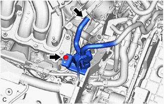
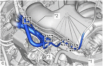
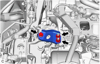
- Disconnect the No. 1 vacuum switching valve assembly (for ACIS) connector.
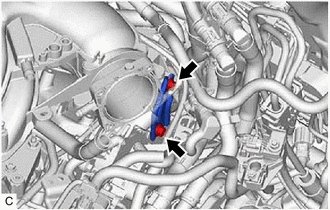
- Disengage the 2 clamps to disconnect the vacuum hose sub-assembly from the intake air surge tank assembly.
- Disengage the 2 clamps to disconnect the vacuum hose sub-assembly from the intake air surge tank assembly.
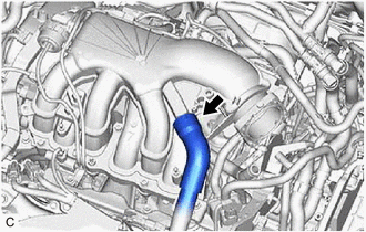
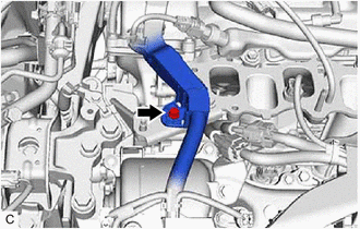
*1 Vacuum Hose Sub-assembly *2 Vacuum Hose *3 No. 2 Air Tube - Disengage the clamp to disconnect the vacuum hose from the intake air surge tank assembly.
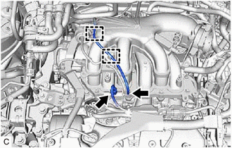
- Disengage the clamp to disconnect the No. 2 air tube from the intake air surge tank assembly.
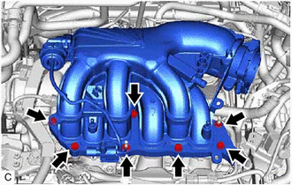
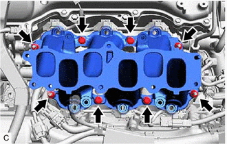
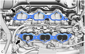
- Remove the 5 bolts, 2 nuts and intake air surge tank assembly from the intake manifold.
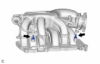
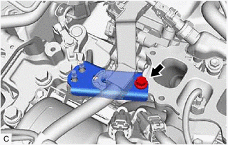
- Disconnect the No. 1 vacuum switching valve assembly (for ACIS) connector.
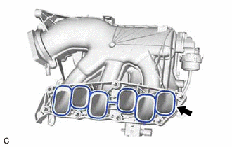
- REMOVE AIR SURGE TANK TO INTAKE MANIFOLD GASKET
- REMOVE NO. 1 V-BANK COVER BRACKET
HINT:
Perform this procedure only when replacement of the No. 1 V-bank cover bracket is necessary.
- REMOVE NO. 2 ENGINE MOUNTING STAY RH
- REMOVE REAR ENGINE MOUNTING STAY RH
- DISCONNECT FUEL TUBE SUB-ASSEMBLY
Refer to PROCEDURE - Step 5
- REMOVE FUEL DELIVERY PIPE WITH SENSOR ASSEMBLY
Refer to PROCEDURE - Step 6
- REMOVE NO. 1 DELIVERY PIPE SPACER
Refer to PROCEDURE - Step 7
- REMOVE INJECTOR VIBRATION INSULATOR
Refer to PROCEDURE - Step 8
- REMOVE INTAKE MANIFOLD
- REMOVE NO. 1 INTAKE MANIFOLD TO HEAD GASKET
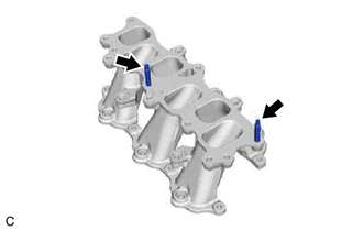
- REMOVE STUD BOLT
HINT:
If a stud bolt is deformed or the threads are damaged, replace it.