DTC P323A-19: Backup Boost Converter "A" Circuit Current Above Threshold [12/2019 - 10/2022]: Procedure
- CHECK ANY OTHER DTCS OUTPUT (IN ADDITION TO DTC P323A-19)
- Read the DTCs.
Powertrain > Stop and Start > Trouble Codes
Result
Result Proceed to DTC P323A-19 is output A DTC P2796-12, P2796-14 or P2797-96 and P323A-19 are output B HINT:
If DTCs P323A-19 and P2796-12, P2796-14 or P2797-96 are output simultaneously, troubleshoot for DTC P2796-12, P2796-14 or P2797-96 first.
Result:
B
GO TO DTC P2796-12, P2796-14 OR P2797-96
Refer to DIAGNOSTIC TROUBLE CODE CHART [12/2019 - 10/2022]
Result:
A
See step 2
- Read the DTCs.
- CHECK HARNESS AND CONNECTOR (ENGINE STOP AND START ECU - BBC NO. 1 FUSE AND BBC NO. 2 FUSE)
- Disconnect the engine stop and start ECU connector.
- Remove the BBC NO. 1 fuse and BBC NO. 2 fuse from the No. 1 engine room relay block and No. 1 junction block assembly.
- Measure the resistance according to the value(s) in the table below.
Standard Resistance
Tester Connection Condition Specified Condition A33-1 (BIN2) - 2 (BBC NO. 2 fuse) Always Below 1 Ω A33-3 (BIN1) - 2 (BBC NO. 1 fuse) Always Below 1 Ω A33-1 (BIN2) or 2 (BBC NO. 2 fuse) - Body ground and other terminals Always 10 kΩ or higher A33-3 (BIN1) or 2 (BBC NO. 1 fuse) - Body ground and other terminals Always 10 kΩ or higher Result
Proceed to OK NG
Result:
NG
REPAIR OR REPLACE HARNESS OR CONNECTOR
Result:
OK
See step 3
- CHECK HARNESS AND CONNECTOR (ENGINE STOP AND START ECU - EACH ECU OR SENSOR)
- Disconnect the engine stop and start ECU connector.
- Remove the FOG FR relay from the No. 1 engine room relay block and No. 1 junction block assembly. (w/ Front Fog Light)
- Disconnect the integration control sub-assembly connector. (w/ 12.3 Inch Display)
- Disconnect the tire pressure warning ECU and receiver connector.
- Disconnect the navigation ECU connector. (w/ Navigation System)
- Disconnect the meter mirror assembly connector. (w/ Headup Display)
- Disconnect the radio and display receiver assembly connector. (w/o 12.3 Inch Display)
- Disconnect the radio receiver assembly connector. (w/ 12.3 Inch Display)
- Disconnect the multi-display assembly connector. (w/ 12.3 Inch Display)
- Disconnect the television display assembly connector. (w/ Rear Seat Entertainment System)
- Disconnect the inner rear view mirror assembly connector. (w/ EC Mirror or Digital Inner Mirror)
- Disconnect the front door ambient light LH (front door trim board sub-assembly LH) connector. (w/ Ambient Illumination Light)
- Disconnect the front door ambient light RH (front door trim board sub-assembly RH) connector. (w/ Ambient Illumination Light)
- Disconnect the rear door ambient light LH (rear door trim board sub-assembly LH) connector. (w/ Ambient Illumination Light)
- Disconnect the rear door ambient light RH (rear door trim board sub-assembly RH) connector. (w/ Ambient Illumination Light)
- Disconnect the front passenger side tray illumination light (No. 1 instrument panel light sub-assembly) connector. (w/ Ambient Illumination Light)
- Disconnect the center tray illumination light (No. 1 instrument panel light sub-assembly) connector. (w/ Ambient Illumination Light)
- Disconnect the air conditioning control assembly connector.
- Disconnect the central gateway ECU (network gateway ECU) connector.
- Disconnect the millimeter wave radar sensor assembly connector.
- Disconnect the clearance warning ECU assembly connector.
- Disconnect the blind spot monitor sensor LH connector.
- Disconnect the blind spot monitor sensor RH connector.
- Disconnect the No. 2 air conditioning control assembly connector.
- Measure the resistance according to the value(s) in the table below.
Standard Resistance
Tester Connection Condition Specified Condition H66-2 (B41) - 2 (FOG FR relay)*1 Always Below 1 Ω H66-2 (B41) - 5 (FOG FR relay)*1 Always Below 1 Ω H66-2 (B41) - H8-1 (B)*3 Always Below 1 Ω H66-2 (B41) - M51-7 (+B) Always Below 1 Ω H66-2 (B41) - H18-10 (+B)*2 Always Below 1 Ω H66-2 (B41) - H31-2 (B)*5 Always Below 1 Ω H66-12 (B42) - H1-4 (+B1)*4 Always Below 1 Ω H66-12 (B42) - H4-4 (+B1)*3 Always Below 1 Ω H66-11 (B43) - H7-12 (B)*3 Always Below 1 Ω H66-11 (B43) - R16-1 (+B)*6 Always Below 1 Ω H66-11 (B43) - R1-6 (B)*7 Always Below 1 Ω H66-11 (B43) - R1-6 (+B)*8 Always Below 1 Ω H66-11 (B43) -J26-2 (+)*10 Always Below 1 Ω H66-11 (B43) -J10-2 (+)*10 Always Below 1 Ω H66-11 (B43) -K10-2 (+)*10 Always Below 1 Ω H66-11 (B43) -K5-2 (+)*10 Always Below 1 Ω H66-11 (B43) -H69-2 (ILL+)*10 Always Below 1 Ω H66-11 (B43) -H68-2 (ILL+)*10 Always Below 1 Ω H66-3 (IG41) - H8-4 (IG+)*3 Always Below 1 Ω H66-3 (IG41) - R1-1 (IG)*9 Always Below 1 Ω H66-3 (IG41) - M51-1 (IG) Always Below 1 Ω H66-3 (IG41) - H31-1 (IG)*5 Always Below 1 Ω H66-3 (IG41) - H27-4 (IG+)*3 Always Below 1 Ω H66-3 (IG41) - H27-6 (IG+)*4 Always Below 1 Ω H66-3 (IG41) - H59-11 (IG1) Always Below 1 Ω H66-3 (IG41) - B6-8 (IGB) Always Below 1 Ω H66-3 (IG41) - H46-1 (IG) Always Below 1 Ω H66-3 (IG41) - M43-5 (BLB) Always Below 1 Ω H66-3 (IG41) - M2-5 (BRB) Always Below 1 Ω H66-3 (IG41) - T2-9 (IG) Always Below 1 Ω H66-2 (B41) or 2 (FOG FR relay)*1 - Body ground and other terminals Always 10 kΩ or higher H66-2 (B41) or 5 (FOG FR relay)*1 - Body ground and other terminals Always 10 kΩ or higher H66-2 (B41) or H8-1 (B)*3 - Body ground and other terminals Always 10 kΩ or higher H66-2 (B41) or M51-7 (+B) - Body ground and other terminals Always 10 kΩ or higher H66-2 (B41) or H18-10 (+B)*2 - Body ground and other terminals Always 10 kΩ or higher H66-2 (B41) or H31-2 (B)*5 - Body ground and other terminals Always 10 kΩ or higher H66-12 (B42) or H1-4 (+B1)*4 - Body ground and other terminals Always 10 kΩ or higher H66-12 (B42) or H4-4 (+B1)*3 - Body ground and other terminals Always 10 kΩ or higher H66-11 (B43) or H7-12 (B)*3 - Body ground and other terminals Always 10 kΩ or higher H66-11 (B43) or R16-1 (+B)*6 - Body ground and other terminals Always 10 kΩ or higher H66-11 (B43) or R1-6 (B)*7 - Body ground and other terminals Always 10 kΩ or higher H66-11 (B43) or R1-6 (+B)*8 - Body ground and other terminals Always 10 kΩ or higher H66-11 (B43) or J26-2 (+)*10 - Body ground and other terminals Always 10 kΩ or higher H66-11 (B43) or J10-2 (+)*10 - Body ground and other terminals Always 10 kΩ or higher H66-11 (B43) or K10-2 (+)*10 - Body ground and other terminals Always 10 kΩ or higher H66-11 (B43) or K5-2 (+)*10 - Body ground and other terminals Always 10 kΩ or higher H66-11 (B43) or H69-2 (ILL+)*10 - Body ground and other terminals Always 10 kΩ or higher H66-11 (B43) or H68-2 (ILL+)*10 - Body ground and other terminals Always 10 kΩ or higher H66-3 (IG41) or H8-4 (IG+)*3 - Body ground and other terminals Always 10 kΩ or higher H66-3 (IG41) or R1-1 (IG)*9 - Body ground and other terminals Always 10 kΩ or higher H66-3 (IG41) or M51-1 (IG) - Body ground and other terminals Always 10 kΩ or higher H66-3 (IG41) or H31-1 (IG)*5 - Body ground and other terminals Always 10 kΩ or higher H66-3 (IG41) or H27-4 (IG+)*3 - Body ground and other terminals Always 10 kΩ or higher H66-3 (IG41) or H27-6 (IG+)*4 - Body ground and other terminals Always 10 kΩ or higher H66-3 (IG41) or H59-11 (IG1) - Body ground and other terminals Always 10 kΩ or higher H66-3 (IG41) or B6-8 (IGB) - Body ground and other terminals Always 10 kΩ or higher H66-3 (IG41) or H46-1 (IG) - Body ground and other terminals Always 10 kΩ or higher H66-3 (IG41) or M43-5 (BLB) - Body ground and other terminals Always 10 kΩ or higher H66-3 (IG41) or M2-5 (BRB) - Body ground and other terminals Always 10 kΩ or higher H66-3 (IG41) or T2-9 (IG) - Body ground and other terminals Always 10 kΩ or higher - *1: w/ Front Fog Light
- *2: w/ Navigation System
- *3: w/ 12.3 Inch Display
- *4: w/o 12.3 Inch Display
- *5: w/ Headup Display
- *6: w/ Rear Seat Entertainment System
- *7: w/ Digital Inner Mirror
- *8: w/ EC Mirror
- *9: w/ EC Mirror or Digital Inner Mirror
- *10: w/ Ambient Illumination Light
Result
Proceed to OK NG
Result:
NG
REPAIR OR REPLACE HARNESS OR CONNECTOR
Result:
OK
See step 4
- CHECK ENGINE STOP AND START ECU
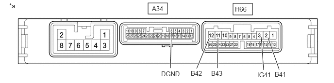
*a Component without harness connected
(Engine Stop and Start ECU)- - - Disconnect the engine stop and start ECU connectors.
- Measure the resistance according to the value(s) in the table below.
Standard Resistance
Tester Connection Condition Specified Condition H66-2 (B41) - A34-6 (DGND) Always 10 kΩ or higher H66-3 (IG41) - A34-6 (DGND) Always 10 kΩ or higher H66-11 (B43) - A34-6 (DGND) Always 10 kΩ or higher H66-12 (B42) - A34-6 (DGND) Always 10 kΩ or higher Result
Proceed to OK NG
Result:
NG
REPLACE ENGINE STOP AND START ECU
Refer to REMOVAL [12/2019 - 10/2022]
Result:
OK
See step 5
- CHECK VEHICLE CONDITION (B41, B42, B43 OR IG41 CIRCUIT)
- Check that additional devices installed to the vehicle (aftermarket audio system, etc.) are not connected to the B41, B42, B43 or IG41 terminal circuit of the engine stop and start ECU.
Result
Result Proceed to Load from an additional device installed to the vehicle (aftermarket audio system, etc.) is not applied. A Load from an additional device installed to the vehicle (aftermarket audio system, etc.) is applied. B
Result:
A
TROUBLESHOOT ECUS CONNECTED TO TERMINALS B41, B42, B43 AND IG41
Result:
B
END (REMOVE ADDITIONAL DEVICE)
- Check that additional devices installed to the vehicle (aftermarket audio system, etc.) are not connected to the B41, B42, B43 or IG41 terminal circuit of the engine stop and start ECU.