DTC P2530-14: Ignition Switch Circuit Short to Ground or Open [11/2023 - ]: Procedure
- READ VALUE USING GTS (IG SWITCH)
- According to the display on the GTS, read the Data List.
Powertrain > Stop and Start > Data List
Tester Display IG Switch Result
Tester Display Result Proceed to IG Switch ON A OFF B
Result:
A
USE SIMULATION METHOD TO CHECK
Refer to HOW TO PROCEED WITH TROUBLESHOOTING [12/2019 - ]
Result:
B
See step 2
- According to the display on the GTS, read the Data List.
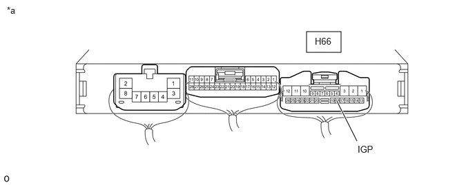
- CHECK ENGINE STOP AND START ECU (IGP TERMINAL VOLTAGE)
*a Component with harness connected
(Engine Stop and Start ECU)- - - Turn the ignition switch to ON.
- Measure the voltage according to the value(s) in the table below.
Standard Voltage
Tester Connection Switch Condition Specified Condition H66-18 (IGP) - Body ground Ignition switch ON 9.5 to 14 V Result
Proceed to OK NG
Result:
NG
See step 5
Result:
OK
See step 3
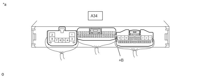
- CHECK ENGINE STOP AND START ECU (+B TERMINAL VOLTAGE)
*a Component with harness connected
(Engine Stop and Start ECU)- - - Turn the ignition switch to ON.
- Measure the voltage according to the value(s) in the table below.
Standard Voltage
Tester Connection Condition Specified Condition A34-1 (+B) - Body ground Ignition switch ON 9.5 to 14 V Result
Proceed to OK NG
Result:
OK
REPLACE ENGINE STOP AND START ECU
Refer to REMOVAL [11/2023 - ]
Result:
NG
See step 4
- CHECK HARNESS AND CONNECTOR (ENGINE STOP AND START ECU - EFI MAIN NO. 1 RELAY)
- Disconnect the engine stop and start ECU connector.
- Remove the EFI-MAIN NO. 1 relay from the No. 1 engine room relay block and No. 1 junction block assembly.
- Measure the resistance according to the value(s) in the table below.
Standard Resistance
Tester Connection Condition Specified Condition A34-1 (+B) - 5 (EFI-MAIN NO. 1 relay holder) Always Below 1 Ω A34-1 (+B) - Body ground and other terminals Always 10 kΩ or higher 5 (EFI-MAIN NO. 1 relay holder) - Body ground and other terminals Always 10 kΩ or higher Result
Proceed to OK NG
Result:
OK
GO TO ECM POWER SOURCE CIRCUIT
Refer to ECM Power Source Circuit [11/2023 - ]
Result:
NG
REPAIR OR REPLACE HARNESS OR CONNECTOR
- CHECK HARNESS AND CONNECTOR (ENGINE STOP AND START ECU - IGP NO. 1 RELAY)
- Disconnect the engine stop and start ECU connector.
- Remove the IGP NO. 1 relay from the No. 1 engine room relay block and No. 1 junction block assembly
- Measure the resistance according to the value(s) in the table below.
Standard Resistance
Tester Connection Condition Specified Condition H66-18 (IGP) - 5 (IGP NO. 1 relay holder) Always Below 1 Ω H66-18 (IGP) - Body ground and other terminals Always 10 kΩ or higher 5 (IGP NO. 1 relay holder) - Body ground and other terminals Always 10 kΩ or higher Result
Proceed to OK NG
Result:
OK
GO TO SMART ACCESS SYSTEM
Refer to Power Source Mode does not Change to ON (IG) [11/2023 - ]
Result:
NG
REPAIR OR REPLACE HARNESS OR CONNECTOR